42
Chapter3 Installation Conditions
F3SJ-E/B
User’s Manual
Wiring/Installation
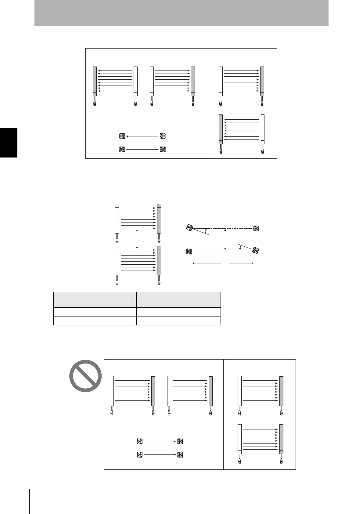
2. Alternate the direction of emission between two sets (alternation)
If two sets of F3SJ-E/Bs are installed near each other, reflection from the surfaces may cause mutual
interference.
3. Keep sufficient distance between the F3SJ-E/Bs so that mutual interference does not occur
When using four or more sets, the installations shown below may cause mutual interference. When
mutual interference occurs, the safety outputs are turned OFF in a moment or the F3SJ-E/B enters
lockout state..
Distance between emitter and
receiver (operating range L)
Allowable installation distance D
0.2 to 3 m 0.26 m
More than 3 m L x tan5° = L x 0.088 (m)
Aligned horizontally
Aligned fore and aft
Aligned vertically
Receiver Emitter Emitter Receiver
Emitter Receiver
Receiver Emitter
Receiver Emitter
Emitter Receiver
Emitter
Receiver
Emitter
Receiver
Emitter Receiver
Emitter Receiver
D
L
D
5°
5°
Emitter Receiver Emitter Receiver
Emitter
Receiver
Emitter
Receiver
Emitter Receiver
Emitter Receiver
Aligned horizontally
Aligned fore and aft
Aligned vertically