11
F3SJ-E/B
User’s Manual
Chapter2 Wiring Diagrams
System Configuration and Functions
E
Wiring Diagrams
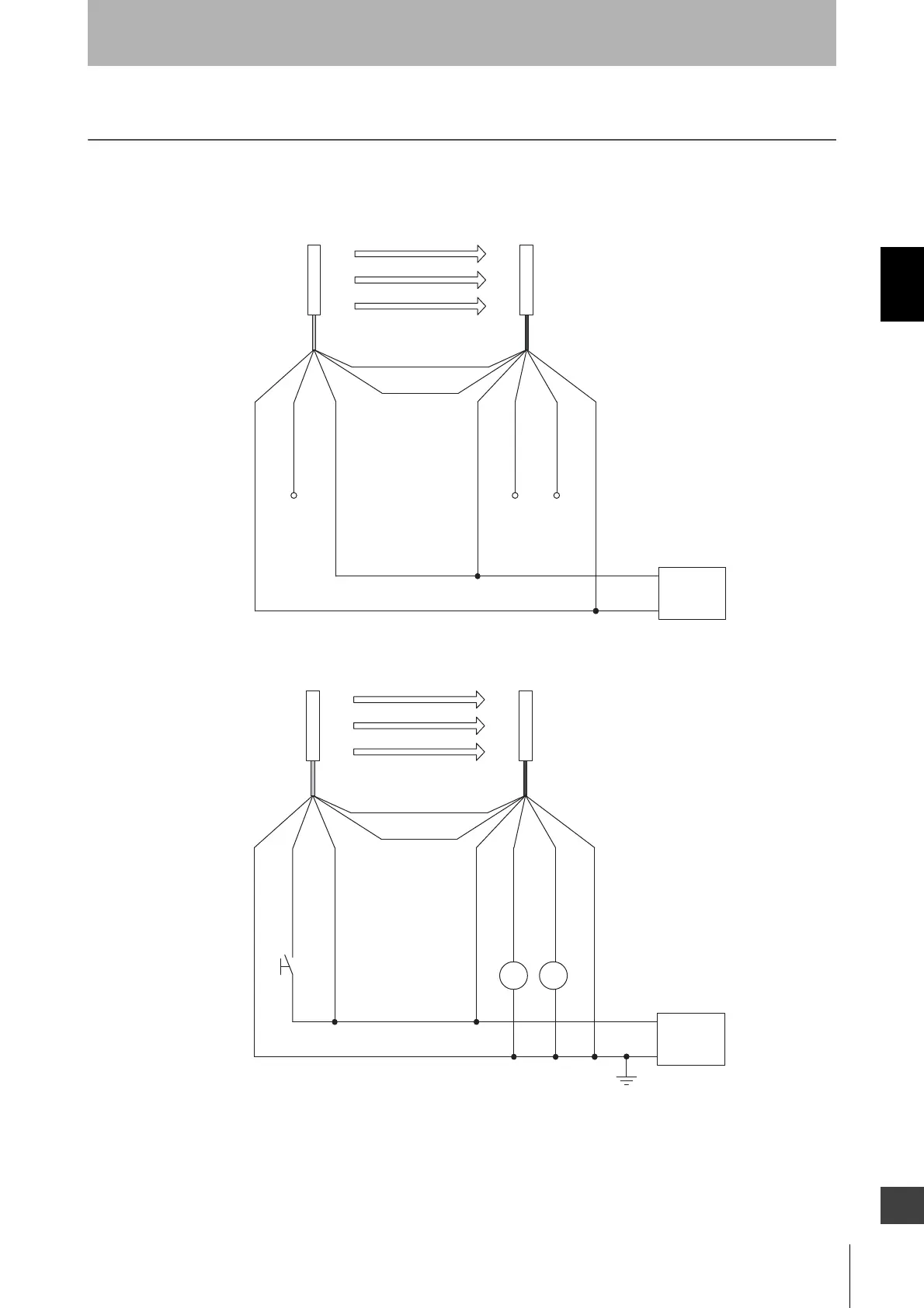
Easy Type
Minimum wiring required to check the operation of the F3SJ-E
Wiring when using test input line
Open
Open
0V
Emitter
Receiver
0 V (Blue)
Open
Test input (Black)
24 V (Brown)
24 V (Brown)
Safety
output 1 (Black)
Safety
output 2 (White)
0 V (Blue)
Power
supply
+24 VDC
(Gray) Communication line (+)
(Pink)
Communication line (-)
0V
Emitter
Receiver
0 V (Blue)
Test input (Black)
24 V (Brown)
24 V (Brown)
Safety
output 1 (Black)
Safety
output 2 (White)
0 V (Blue)
Power
supply
+24 VDC
(Gray) Communication line (+)
(Pink)
Communication line (-)
S1
*1
KM1
KM2
S1 : External test/lockout reset switch (connect to 0 V if a switch is not required)
KM1, KM2 : Safety relay with force-guided contact (G7SA) or magnetic contactor
*1. Use a switch for small loads (input specifications: 24 V, 3 mA).