107
F3SJ-E/B
User’s Manual
Chapter4 Wiring Examples
Input/Output Circuit and Applications
E
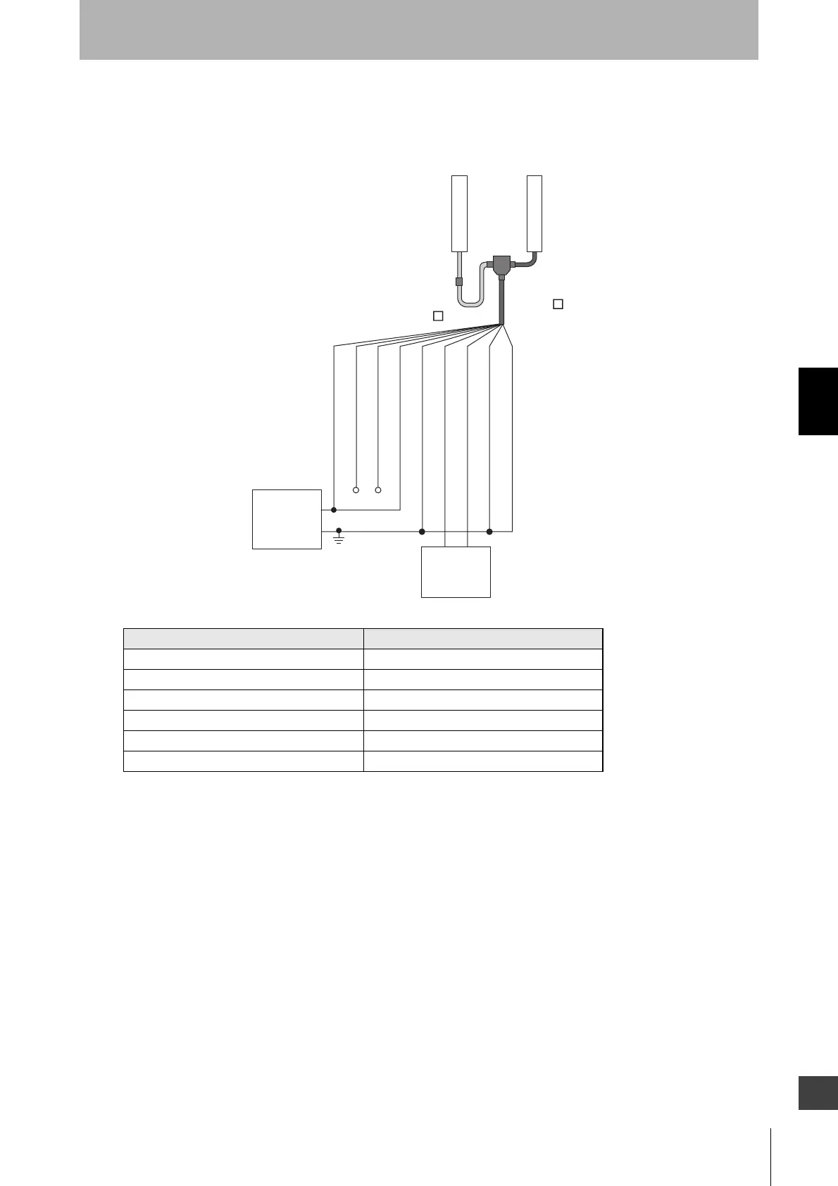
Using a reduced wiring connector for F3SJ-B
•A combination of a cable for reduced wiring (F39-JDBA) and a reduced wiring connector (F39-CN5)
can be used for a reduced wiring system.
An example of a control unit connectable to F3SJ-B
Safety Controller Model
Safety Network Controller NE1A Series
Safety Controller G9SP Series
Flexible Safety Unit G9SX
Safety Guard Switching Unit G9SX-GS
Safety Relay Unit G9SA Series/ G9SB Series
Control Unit F3SP-B1P
F39-JD A-D
F39-CN5
Receiver
Emitter
F39-JD B-L
+24V DC
0V
Power
supply
0V (Blue)
Shield
+24V (Brown)
Test input (Red)
Reset input (Yellow)
Safety output 1 (Black)
Safety output 2 (White)
Communication line (+) (Grey)
Communication line (-) (Pink)
Safety
controllers,
etc.