106
Chapter4 Wiring Examples
F3SJ-E/B
User’s Manual
Input/Output Circuit and Applications
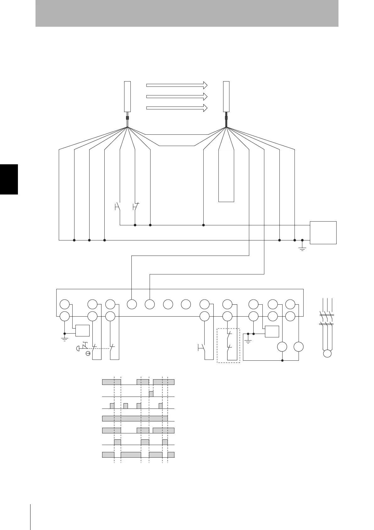
Connecting a F3SJ-B to a G9SP
•Emergency stop switch can be connected
•Door switch, two hand control, single beam sensor, or relay unit can be used in combination with
G9SP.
S3 S4
+24 V (Brown)
Interlock select input (White)
Reset input (Yellow)
External device
monitoring input (Red)
Auxiliary output (Yellow)
Shield
Shield
Not used (Red)
+24 VDC
0 V
Power
supply
V1 Si0 Si1
G1
GND
S1
T0
11
12
22
21
T1
Si2 Si3 Si4 Si5 Si6 Si7
T2
T3
So0 So1V2
G2
G2
G2
S2
M
KM1
KM2
GND
KM1
KM1
KM2
KM2
S1
S2
S3
S4
KM1, KM2
M
: Emergency stop switch
(force-opening contact) (A165E, A22E)
: Reset switch
: External test switch (connect to 0 V if a switch is not required)
: Lockout reset switch (connect to 24 V if a switch is not required)
: Safety relay with force-guided contact (G7SA)
or magnetic contactor
: 3-phase motor
Receiver
Emitter
Communication line (+) (Gray)
Communication line (-) (Pink)
0 V (Blue)
Test input (Black)
+24 V (Brown)
Safety output 1 (Black)
Safety output 2 (White)
0 V (Blue)
F39-JDA-L F39-JDA-D
+24 VDC
0 V
Power
supply
+24 VDC
0 V
Power
supply
KM1,KM2 N.C. contact
Unblocked
Blocked
External test switch
(S3)
Reset switch
(S2)
Safety output
KM1,KM2 N.O. contact
Emergency stop switch
(S1)
- F3SJ-B settings
- Auto reset mode
- Does not use external device
monitoring function
- G9SP settings
- Manual reset mode
- Using feedback loop
Feedback loop