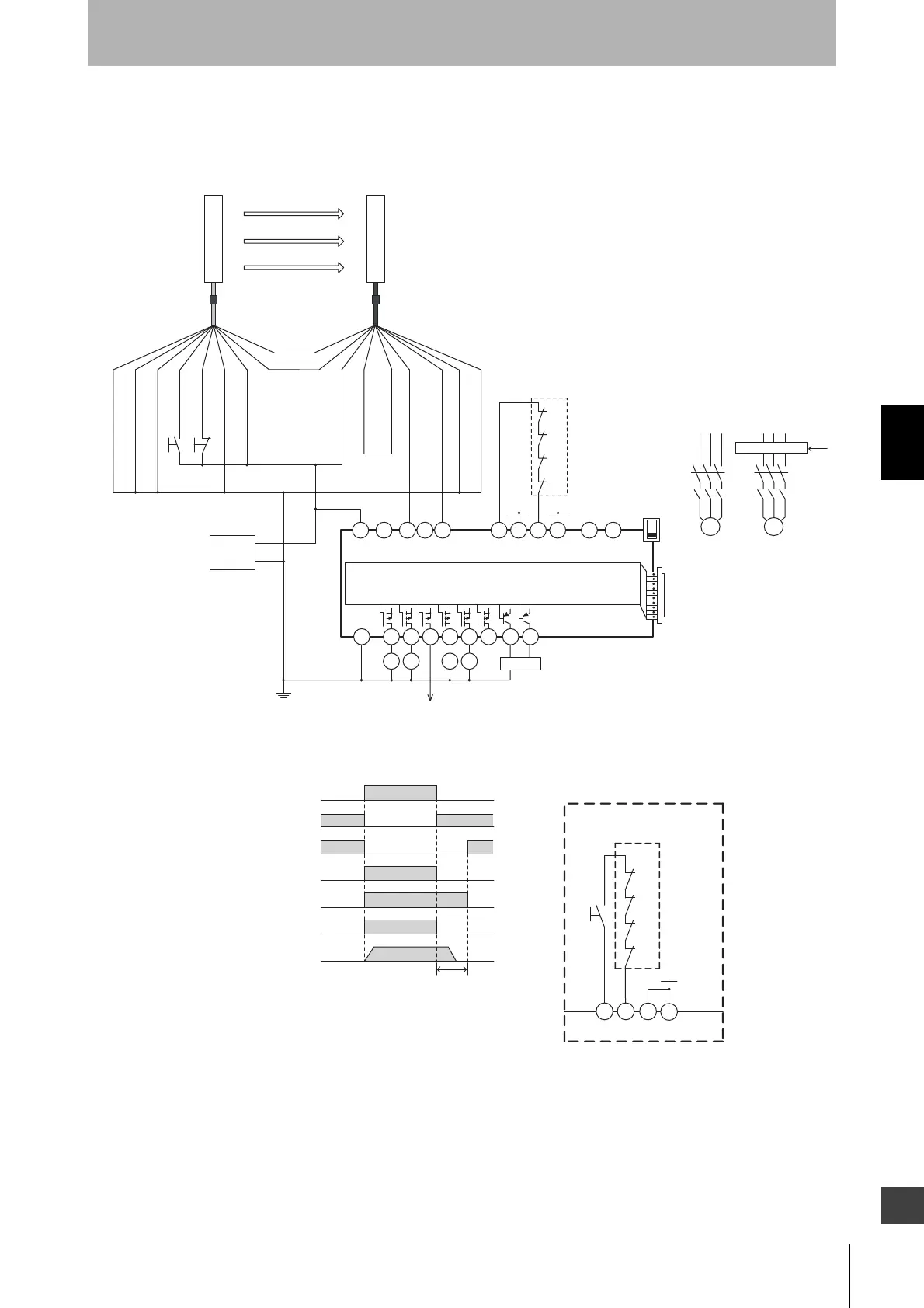
A1
A2
S14 S24
KM1 KM2
S34 S44 S54
KM3 KM4
L1 X1 X2
T11
KM1
KM2
KM3
KM4
+24 V +24 V
T12 T21 T22 T31 T32 T33 Y1 T41 T42
M1 M2
PLC, etc.
Motor controller
Motor controller
(operation command)
Feedback loop
Open
G9SX-AD322-T15
Open Open Open
OFF
AND
KM1
KM2
KM3
S34
KM4
Control circuit
S1 : External test switch
(connect to 0 V if a switch is not required)
S2
: Lockout reset switch
(connect to 24 V if a switch is not required)
KM1 ~
KM4 :
KM1 to KM4: Safety relay with force-guided contact (G7SA)
or magnetic contactor
M1,M2 : 3-phase motor
PLC : Programmable controller
(Used for monitoring -- not related to safety system)
Safety output
KM1,KM2 N.C. contact
KM3,KM4 N.C. contact
KM1,KM2 N.O. contact
KM3,KM4 N.O. contact
Motor operation command
Motor rotation
OFF-delay time
- F3SJ-B settings
- Auto reset mode
- Does not use external device monitoring function
- G9SX-AD322-T15 settings
- Auto reset mode
- Using feedback loop
+24 V (Brown)
0 V (Blue)
Safety output 1 (Black)
Safety output 2 (White)
Auxiliary output (Yellow)
S1
S2
Shield
0 V (Blue)
Test input (Black)
Reset input (Yellow)
Interlock select input (White)
+24 V (Brown)
Communication
line (+) (Gray)
Communication
line (-) (Pink)
External device
monitoring input (Red)
Shield
+24 VDC
0 V
Power
supply
Not used (Red)
+24 V
T32 T33
Y1
KM3
KM4
T31
KM1
KM2
S3
Wiring for manual reset mode
Feedback loop
S3: Reset switch
Receiver
Emitter
F39-JDA-L F39-JDA-D