OUT
PLC
IN
Not Used (Red)
S1
S2
Interlock
select
input (White)
KM1
KM2
KM1
KM2
Power
Supply
+24 VDC
0 V
M
KM2
KM1
KM3
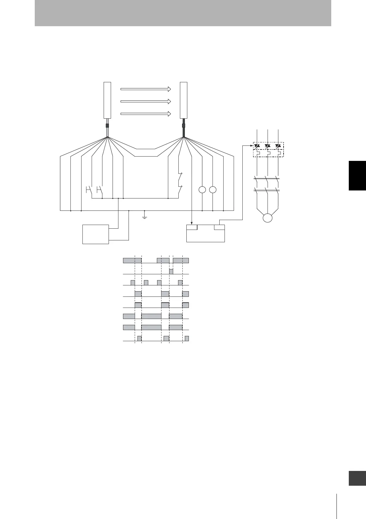
Unblocked
Blocked
External test switch (S1)
Reset switch (S2)
Safety output
KM1,KM2 N.O. contact
KM1,KM2 N.C. contact
PLC input *
PLC output
- Manual reset mode
- Using external device monitoring function
S1 :External test switch (connect to 0V if a switch is not required)
S2 :Interlock/lockout reset switch
KM1, KM2 :Safety relay with force-guided contact (G7SA)
or magnetic contactor
KM3 :Solid state contactor (G3J)
M :3-phase motor
PLC :Programmable controller
(Used for monitoring -- not related to safety system)
* Auxiliary output gives inverted signal of safety output.
Emitter
Receiver
F39-JDA-L F39-JDA-D
Communication
line (+) (Gray)
Communication
line (-) (Pink)
Shield
0 V (Blue)
Test input
(Black)
Reset input
(Yellow)
+24 V (Brown)
+24 V (Brown)
External device
monitoring input (Red)
Auxiliary output (Yellow)
Safety output 1
(Black)
Safety output 2
(White)
0 V (Blue)
Shield