you use.
S1B1 A1 S3
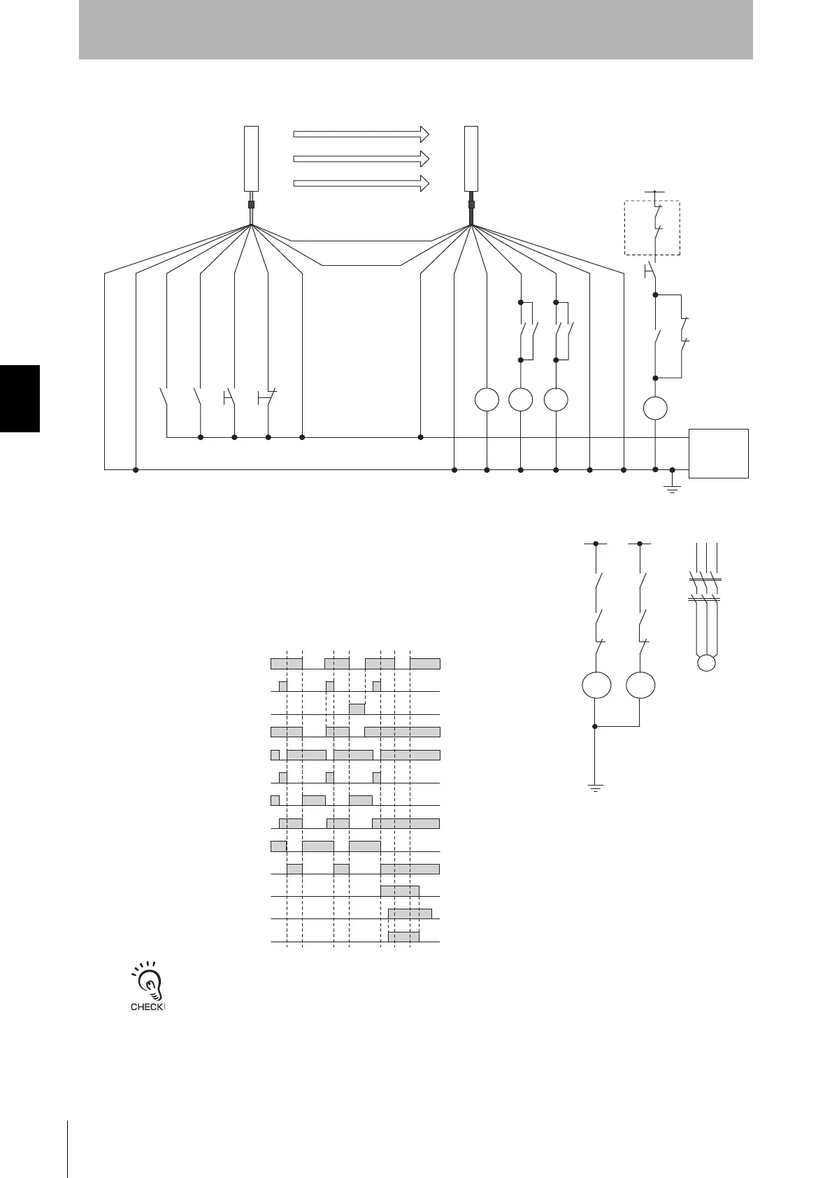
Reset input (Yellow)
*1
*2
*1
Muting input 2 (Red)
ML K1 K2
K3
+24 VDC
0 V
- Does not use external device
monitoring function
KM2
K3
K2
K1
KM1
K3
K2
K1
+24 V +24 V
KM1
KM2
+24 V
Feedback loop
K1
K2
S2
K3
K3K1 K3K2
M
KM1
KM2
Shield
0 V (Blue)
Muting input 1 (White)
Test input (Black)
+24 V (Brown)
+24 V (Brown)
External device monitoring input (Red)
Auxiliary output
(Yellow)
Safety output 1
(Black)
Safety output 2 (White)
0 V (Blue)
Shield
Communication line (+) (Gray)
Communication line (-) (Pink)
Receiver
Emitter
Power
supply
S1 : External test switch (connect to 0 V if a switch is not required)
S2 : Reset switch
S3 : Lockout reset switch (connect to 24 V if a switch is not required)
A1 : Contact by muting sensor A1
B1 : Contact by muting sensor B1
K1,K2,K3 : Safety relay with force-guided contact (G7SA)
KM1,KM2 : Safety relay with force-guided contact (G7SA) or magnetic contactor
ML : External indicator
M : 3-phase motor
*1. Also used for override input.
*2. Under muting system, connect to 0 V as the external device monitoring cannot be used.
F39-JDA-L
F39-JDA-D
Muting input 1
External indicator
KM1,KM2 N.C. contact
K3 N.C. contact
Unblocked
Blocked
Reset switch
(S2)
External test switch
(S1)
Safety output
K1,K2 N.O. contact
KM1,KM2 N.O. contact
K1,K2 N.C. contact
K3 N.O. contact
Muting input 2