84
Chapter3 Wiring
F3SJ-E/B
User’s Manual
Wiring/Installation
Wiring Method (Easy Type)
Directly wire the single-ended cable that is routed from the sensor.
<F3SJ cable> (The figure shown below is the cable for the emitter.)
To extend the cable, the following specifications must be satisfied.
<Extension cable>
Refer to "<Extension cable>" on page 87.
Wiring Method (Basic Type)
Perform wiring according to the following procedure.
1. Connect an emitter cable (F39-JD-L, gray, sold separately) to the emitter's connection cable (gray).
2. Connect a receiver cable (F39-JD-D, black, sold separately) to the receiver's connection cable
(black).
3. Connect the 0 V line of the power supply directly to the protective earth (PE).
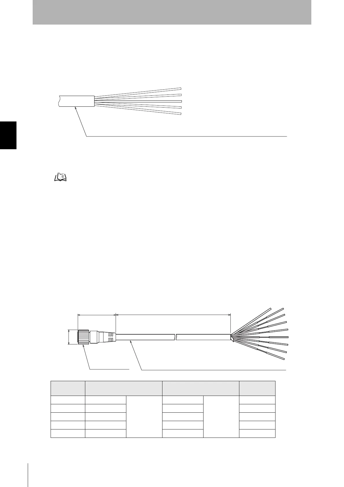
Single-ended connector cable (F39-JDA, sold separately)
Set model
name
Emitter cable Receiver cable L (mm)
F39-JD3A F39-JD3A-L Gray cable F39-JD3A-D Black cable 3000
F39-JD7A F39-JD7A-L F39-JD7A-D 7000
F39-JD10A F39-JD10A-L F39-JD10A-D 10000
F39-JD15A F39-JD15A-L F39-JD15A-D 15000
F39-JD20A F39-JD20A-L F39-JD20A-D 20000
Insulated vinyl round cord dia. 6
Emitter: 5-wire, Receiver: 6-wire (Cross section of conductor: 0.15mm
2
/ Insulator diameter: 1mm)
Insulated vinyl round cable dia. 6.6, shielded 8-wire (4-pair)
(Cross section of conductor: 0.3mm
2
/insulator diameter: dia. 1.15mm)
dia.15
39.5
L
M12 IP67 connector
(Unit: mm)