87
F3SJ-E/B
User’s Manual
Chapter3 Wiring
Wiring/Installation
E
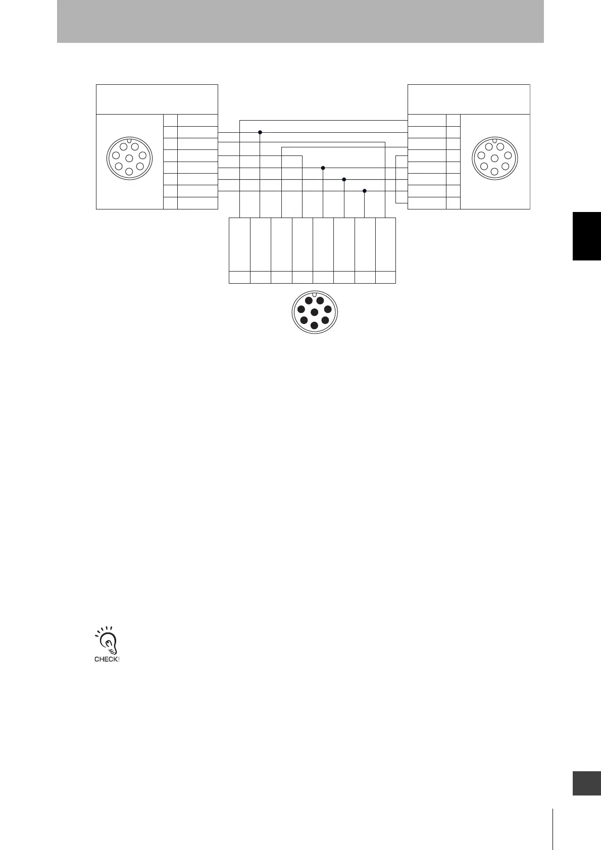
Internal Wiring Diagram (Optional: F39-CN5)
When you need to use a cable that is not specified by OMRON, use a cable that satisfies the following
specifications.
<Extension cable>
Easy Type
1. Emitter : 5-wire (0.12 mm
2
or larger x 1 pair, 0.12 mm
2
or larger x 3, conductor resistance 0.146
ohms/m max.)
Receiver : 6-wire (0.12 mm
2
or larger x 3 pairs, conductor resistance 0.146 ohms/m max.)
2. Emitter : Communication lines (+) and (-) must be used as twisted-pair lines.
Receiver : Communication lines (+) and (-), safety output lines 1 and 2 must be used as twisted-pair
lines.
Basic Type
1. 8-wire (0.3 mm
2
or larger x 4 pairs, conductor resistance 0.058 ohms/m max.)
2. Braided shield
3. Connect the pin No. 7 with the shield line.
4. Communication lines (+) and (-), 24 V and 0 V lines must be used as twisted-pair lines.
Do not use cables in the same conduit as high voltage or electric power lines.
1
2
3
4
5
6
7
8
1
7
8
2
3
4
5
6
1
7
8
2
3
4
5
6
2
3
8
1
7
6
5
4
1
2
3
4
5
6
7
8
123 4567 8
White
Brown
Black
Yellow
Grey
Pink
Blue
Red
Female Female
White
Brown
Black
Yellow
Grey
Pink
Blue
Red
Male
Connected to emitter's connection cable
and Cable with connectors on both ends
Connected to receiver's connection cable
and Cable with connectors on both ends
0V
+24V DC
Test input
Reset input
Safety
output 1
Safety
output 2
Communication
line (+)
Communication
line (-)