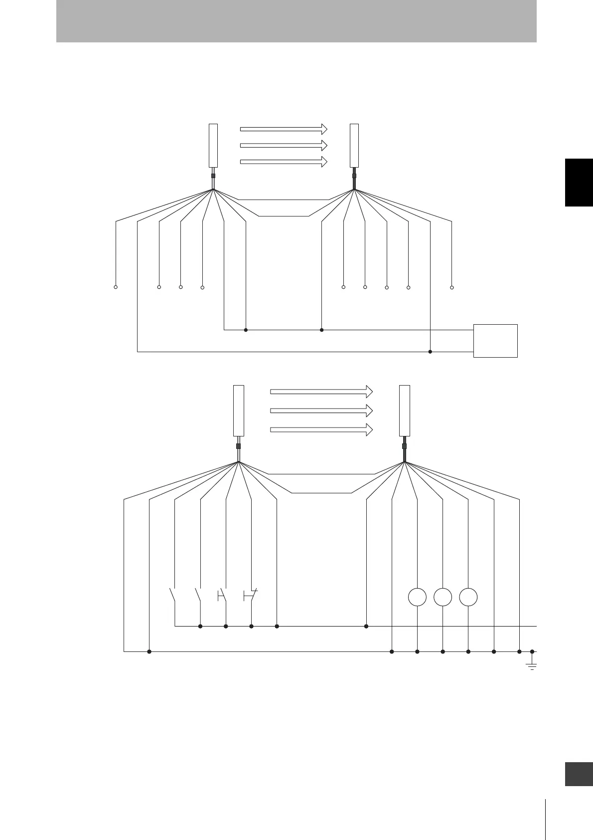
24 V (Brown)
External device monitoring input (Red)
*2
0 V (Blue)
Auxiliary output (Yellow)
Safety output 1 (Black)
Safety output 2 (White)
Shield
Test input (Black)
*1
Reset input (Yellow)
*1
24 V (Brown)
Shield
0 V (Blue)
(Gray) Communication line (+)
(Pink)
Communication line (-)
S1
S2
A1
B1
KM1, KM2
K1
: External test switch
(connect to 0 V if a switch is not required)
: Lockout reset switch (connect to 24 V if a switch is not required)
: Contact by muting sensor A1
: Contact by muting sensor B1
: Safety relay with force-guided contact (G7SA) or magnetic contactor
:
Indicator or PLC, etc. (for monitoring)
S1
B1 A1
S2
K1 KM1
KM2
Emitter
Receiver
Muting input 1 (white)
Muting input 2 (Red)
*1.
Used as override input as well.
*2.
When muting system is used, connect it to 0 V as the external device monitoring function cannot be used.
*3. Use a switch for small loads (input specifications: 24 V, 3 mA).
*4. F3SJ operates even when K1 is not connected.
F39-JDA-L F39-JDA-D
*3 *3
*4