14
Chapter2 Wiring Diagrams
F3SJ-E/B
User’s Manual
System Configuration and Functions
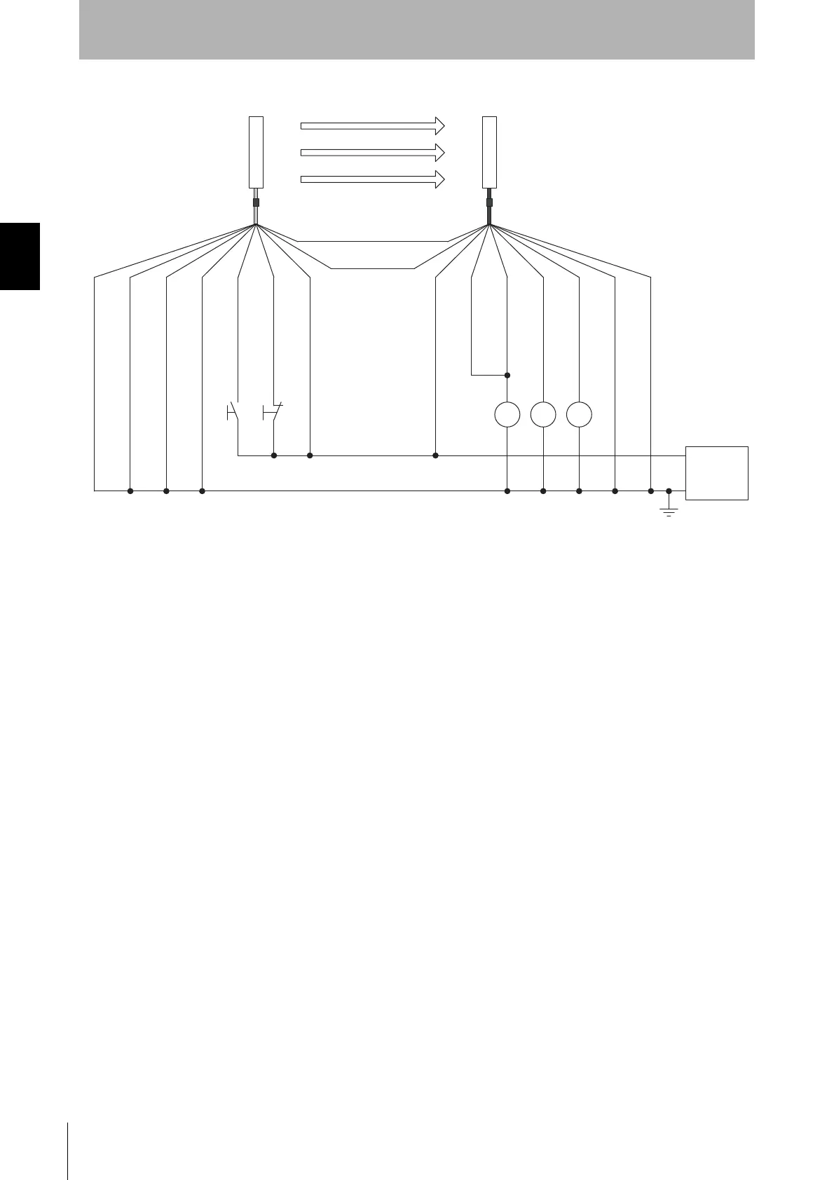
Wiring for auto reset mode and deactivated external device monitoring function
24 V (Brown)
External device monitoring input (Red)
0 V (Blue)
Auxiliary
output (Yellow)
Safety output 1 (Black)
Safety output 2 (White)
Shield
S1
S2
KM1, KM2
K1
: External test switch (connect to 0 V if a switch is not required)
: Lockout reset switch (connect to 24 V if a switch is not required)
: Safety relay with force-guided contact (G7SA) or magnetic contactor
: Load or PLC, etc. (for monitoring)
hield
Not Used (Red)
0 V (Blue)
Interlock select input (White)
Test input (Black)
Reset input (Yellow)
24 V (Brown)
S1 S2
K1 KM1 KM2
0 V
Emitter
Receiver
(Gray) Communication line (+)
(Pink)
Communication line (-)
Power
supply
+24 VDC
F39-JDA-L F39-JDA-D
*1 *1
*2
*1. Use a switch for small loads (input specifications: 24 V, 3 mA).
*2. F3SJ operates even when K1 is not connected.