102
Chapter4 Wiring Examples
F3SJ-E/B
User’s Manual
Input/Output Circuit and Applications
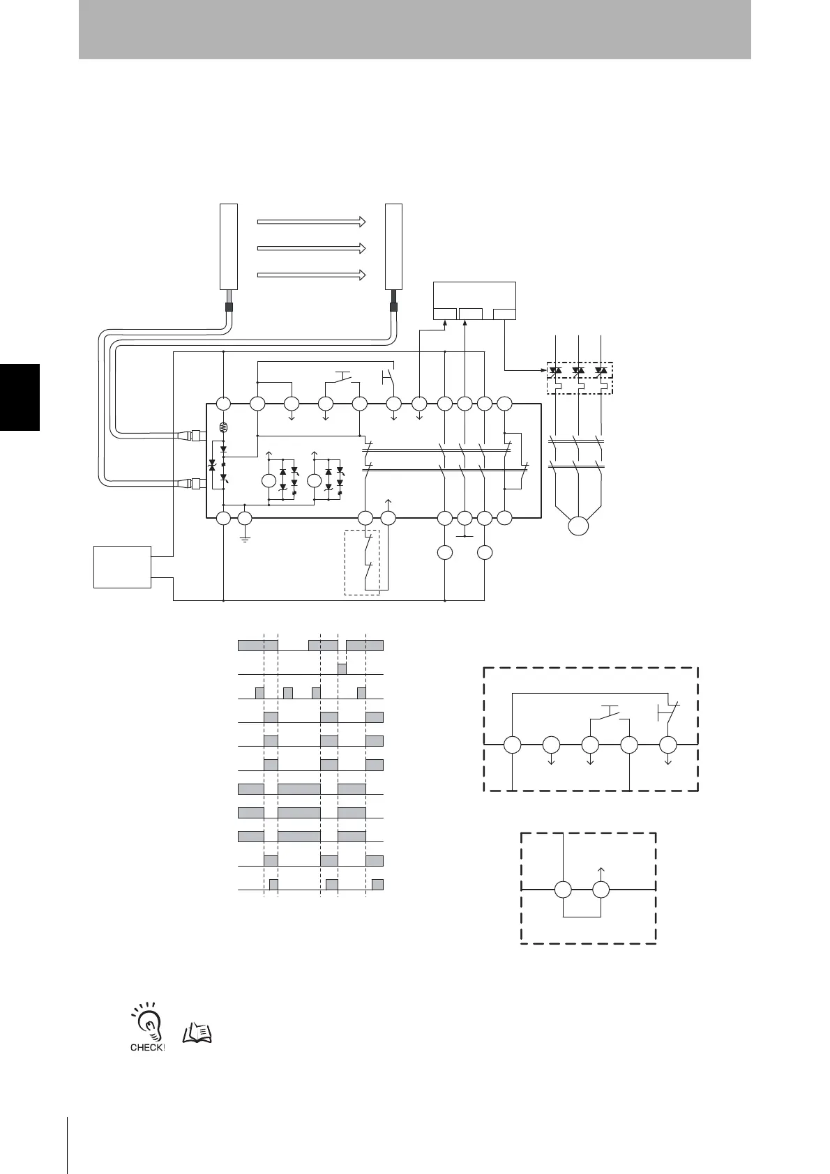
Connecting a F3SJ-B to Various Controllers
Connecting a F3SJ-B to an F3SP-B1P
•Connector can reduce wiring time
•Safety relay included
- It cannot be used as a muting system when F3SP-B1P is used.
Muting Function p.22
PLC
IN1 IN2 OUT
S1
S2
A1 H1 L1 J1 H1 X1 P1 13 23 33 41
KM3
KM1
KM2
Interlock
select
Test
Reset Auxiliary
output
Safety
output 1
Safety
output 2
K1
K2
K1 K2
A2 PE T31 T32
External device
monitoring
14 24 34 42
KM1
KM2
KM1
KM2
F3SP-B1P
Power
supply
+24 VDC
0 V
- Manual reset mode
- Using external device monitoring function
Unblocked
Blocked
External test switch (S1)
Reset switch (S2)
Safety output
K1,K2 N.O. contact
KM1,KM2 N.O. contact
K1,K2 N.C. contact
KM1,KM2 N.C. contact
PLC input 1 *
PLC input 2
PLC output
S1 : External test switch
S2 : Interlock/lockout reset switch
KM1, KM2 : Safety relay with force-guided contact (G7SA)
or magnetic contactor
KM3 : Solid state contactor (G3J)
M : 3-phase motor
PLC : Programmable controller
(Used for monitoring -- not related to safety system)
M
* Auxiliary output gives inverted signal
of safety output.
S2
X1H1J1L1H1
Interlock
select
Reset
Test
S1
Wiring for auto reset mode
T32T31
Wiring when not using external device monitoring function
External device
monitoring
Standard short-circuit bar
Feedback loop
Receiver
Emitter
F39-JDB-L
F39-JDB-D
+24 V