92
Chapter4 Wiring Examples
F3SJ-E/B
User’s Manual
Input/Output Circuit and Applications
Wiring Examples
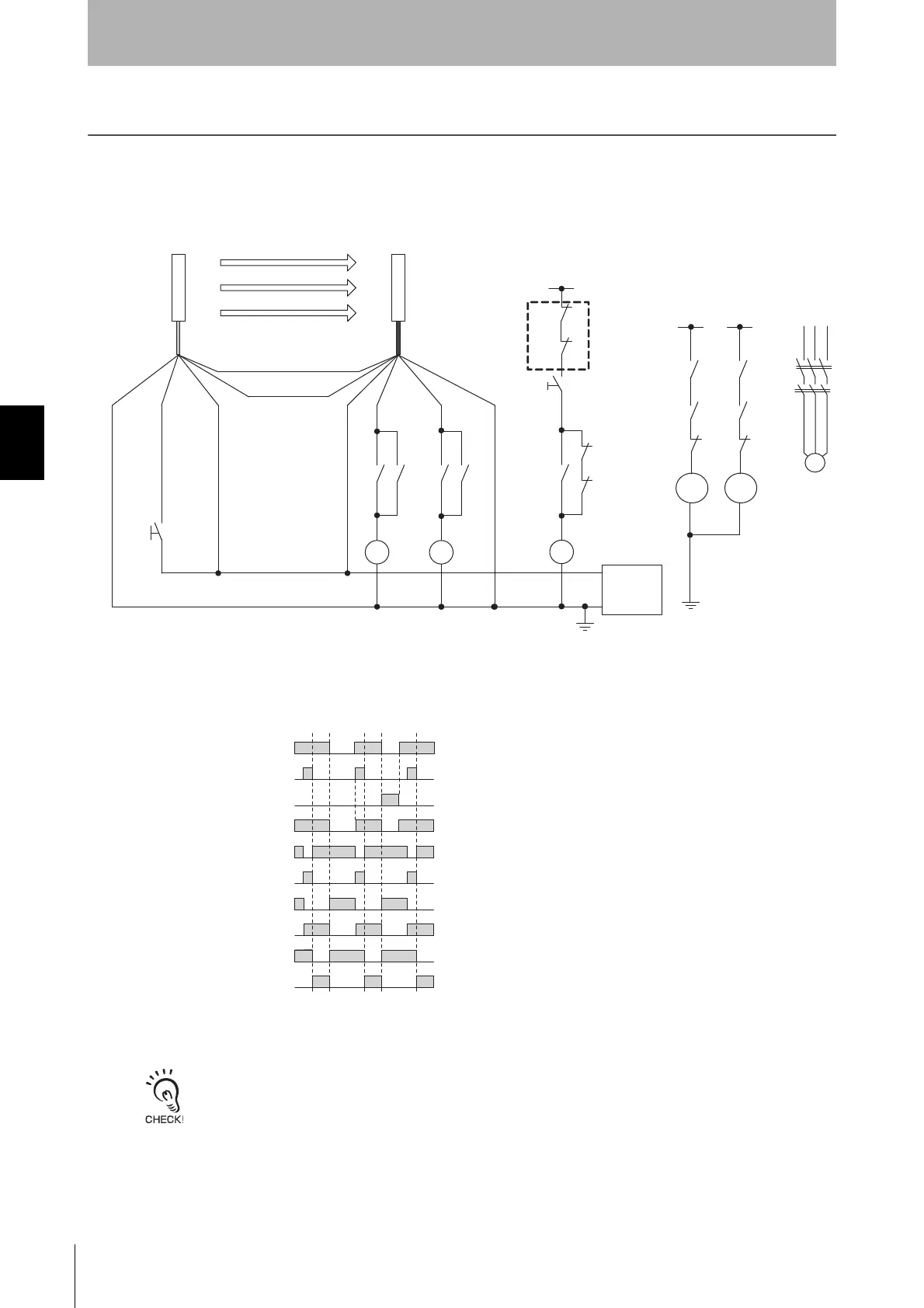
Examples of a motor control system using the F3SJ-E/B are shown below. This chapter shows examples
equivalent to ISO 13849-1 (Category 4, PLe).
Using F3SJ-E Only
Enable reset switch S2 for long enough with the consideration of the operating time or recovery time of each relay that
you use.
S1
K1
K 3
K2
K3
K1
K1 K3 K3 K2
KM1
KM2
S2
+24 V
Feedback loop
KM2
K3
K2
K1
KM1
K3
K2
K1
+24 V +24 V
S1
S2
K1, K2, K3
KM1, KM2
M
: External test/lockout reset switch (connect to 0 V if a switch is not required)
: Reset switch
: Safety relay with force-guided contact (G7SA)
: Safety relay with force-guided contact (G7SA) or magnetic contactor
: 3-phase motor
K2
+24 VDC
0 V
Power
supply
M
KM1
KM2
KM1,KM2 N.C. contact
K3 N.C. contact
Unblocked
Blocked
Reset switch
(S2)
External test/lockout reset switch
(S1)
Safety output
K1,K2 N.O. contact
KM1,KM2 N.O. contact
K1,K2 N.C. contact
K3 N.O. contact
Communication line (+) (Gray)
Communication line (-) (Pink)
Receiver
Emitter
0 V (Blue)
Test input (Black)
+24 V (Brown)
+24 V (Brown)
Safety output 1
(Black)
Safety output 2
(White)
0 V (Blue)