47
F3SJ-E/B
User’s Manual
Chapter3 Dimensions
Wiring/Installation
E
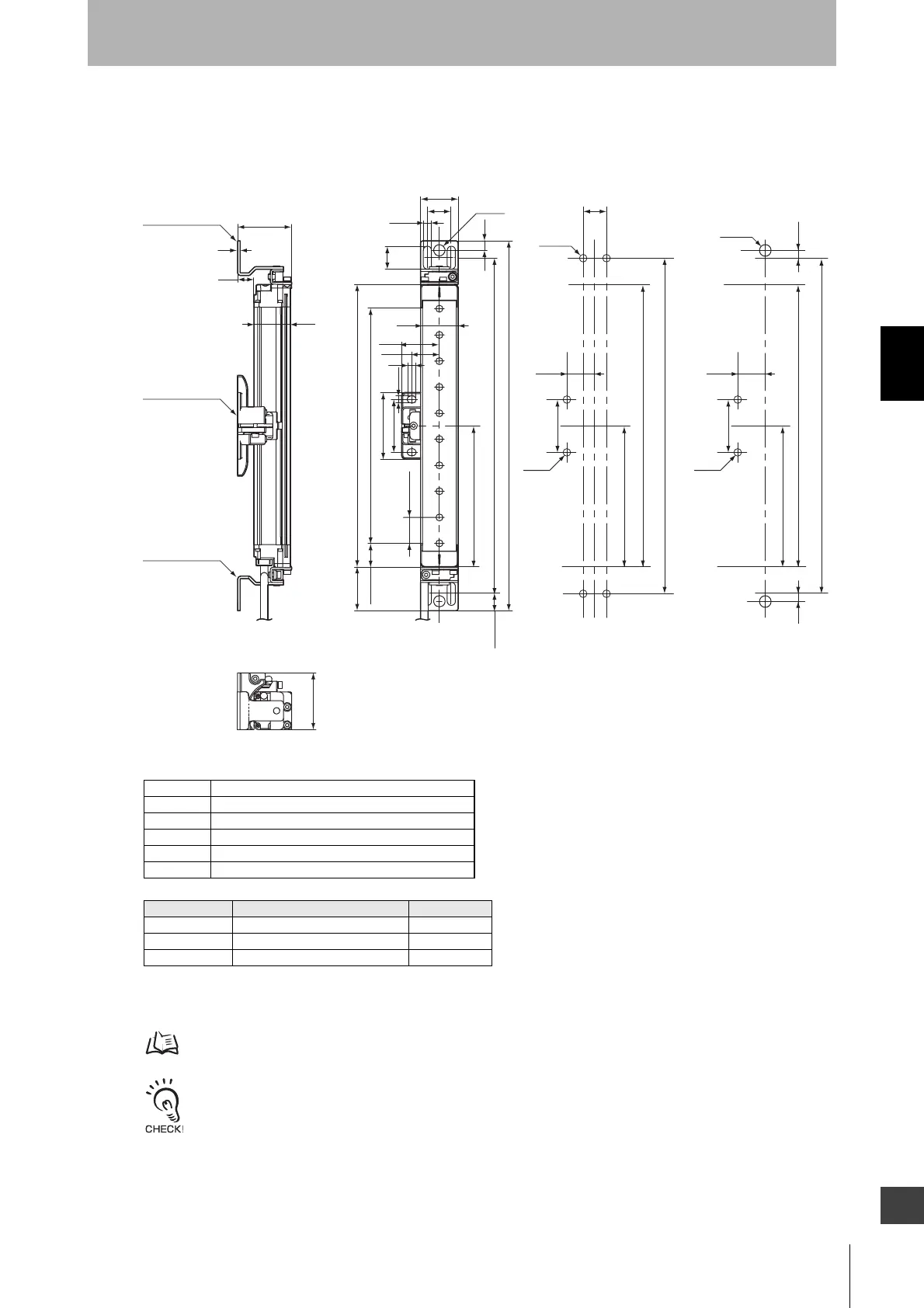
When Using Top/Bottom and Intermediate Brackets
Backside mounting
Bracket mounting procedure (Mounting) p.67
- If the protective height is 1105 mm or more, use Intermediate Brackets of specified quantities and locations
according to the dimensions. If the brackets described above are not used, ratings and performance cannot be met.
- When you use a sensor in a situation where the sensor is under a load, add an Intermediate Bracket.
P (beam gap)
[ Unit : mm ]
13.4
22.5
34.5
B
A
5.5
30
19
6.5
dia.9
7.5
18.3
7
22
30
30
D
53
42
C (Protective height)
30
13
2
43
6.5
45
<M5 screw fixed> <M8 screw fixed>
Top/Bottom Bracket
(F39-LJB1)
Top/Bottom Bracket
(F39-LJB1)
Intermediate Bracket
(F39-LJB2)
2
E
19
B
B
E
C
C
E
42
42
5.9 5.9
22 22
4-M5
2-M8
2-M5 2-M5
Dimensions A to E and P
Dimensions E
* Value E must be 700 mm or less when not using value E obtained from the calculation above.
AC+69
B C+42.2
C 4-digit number of the type name (protective height)
DC-45
E Depends on the protective height. See the table below.
P20
Protective height Number of Intermediate Brackets Dimensions E
0185 to 1105 0 -
1185 to 1345 1 C/2 max.
1425 to 2065 2 C/3 max.