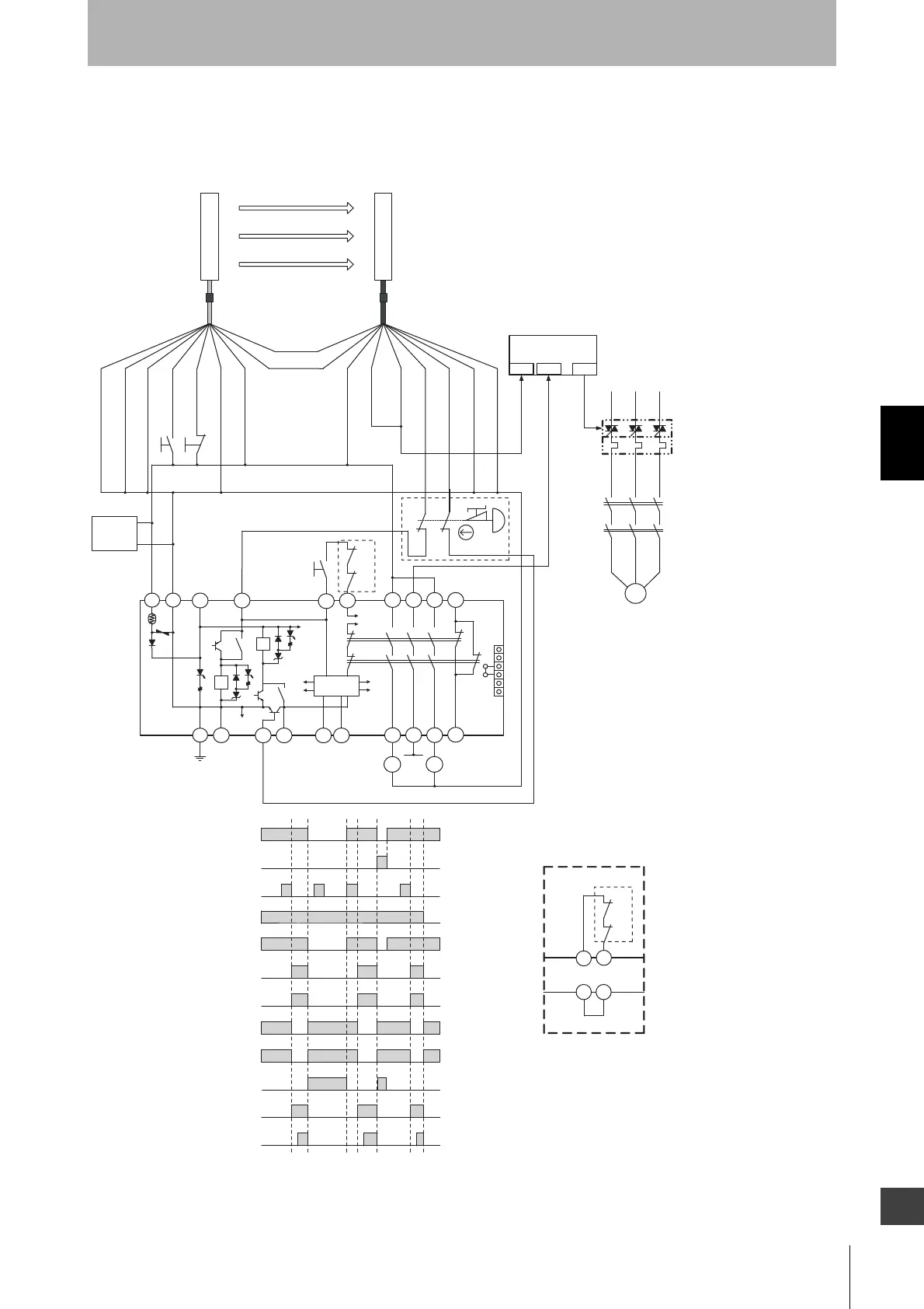
Unblocked
Blocked
External test switch
(S1)
Interlock reset switch
(S2)
Emergency stop switch
(S3)
Safety output
K1,K2 N.O. contact
KM1,KM2 N.O. contact
K1,K2 N.C. contact
KM1,KM2 N.C. contact
PLC input 1 *
PLC input 2
PLC output
Model G9SA-301
Communication
line (+) (Gray)
Communication
line (-) (Pink)
F39-JDA-L
F39-JDA-D
S1
S4
IN1 IN2 OUT
PLC
KM3
M
KM1
KM2
+24 VDC
0 V
A1 A2
T11 T12
S2
KM1
KM2
T31
- F3SJ-B settings
- Auto reset mode
- Does not use external device monitoring function
- G9SA-301 settings
- Manual reset mode
- Using feedback loop
- Using emergency stop switch
K1
3
4
K2
1
a
b
2
5
T32
41
33
23
13
1
2
3
4
5
6
JP
6
a
b
K1
K2
K1
K2
PE T21
T23 T22
A
B
14 24 34 42
Control
Circuit
KM2
*1 If an emergency stop switch is not used, connect safety output 1 to
T12 terminal and safety output 2 to T23 directly.
S1 : External test switch(connect to 0 V if a switch is not required)
S2 : Interlock reset switch
S3 :
Emergency stop switch (force-opening contact) (A165E, A22E)
S4 : Lockout reset switch
(connect to 24V if a switch is not required)
KM1, KM2 : Safety relay with force-guided contact (G7SA)
or magnetic contactor
KM3 : Solid state contactor (G3J)
M : 3-phase motor
PLC : Programmable controller
(Used for monitoring -- not related to safety system)
*1
11
12
21
22
S3
KM1
* Auxiliary output gives inverted signal of safety output.
T32T31
KM1
KM2
A B
Wiring for auto reset mode
Feedback loop
Feedback loop
Emitter
Receiver
Not Used (Red)
Interlock select input (White)
Shield
0 V (Blue)
Test input (Black)
Reset input (Yellow)
+24 V (Brown)
+24 V (Brown)
External device
monitoring input (Red)
Auxiliary
output
(Yellow)
Safety output 1
(Black)
Safety output 2
(White)
0 V (Blue)
Shield
Power
supply
+24 V