85
F3SJ-E/B
User’s Manual
Chapter3 Wiring
Wiring/Installation
E
<Internal wiring diagram> (F39-JDA-L, F39-JDA-D)
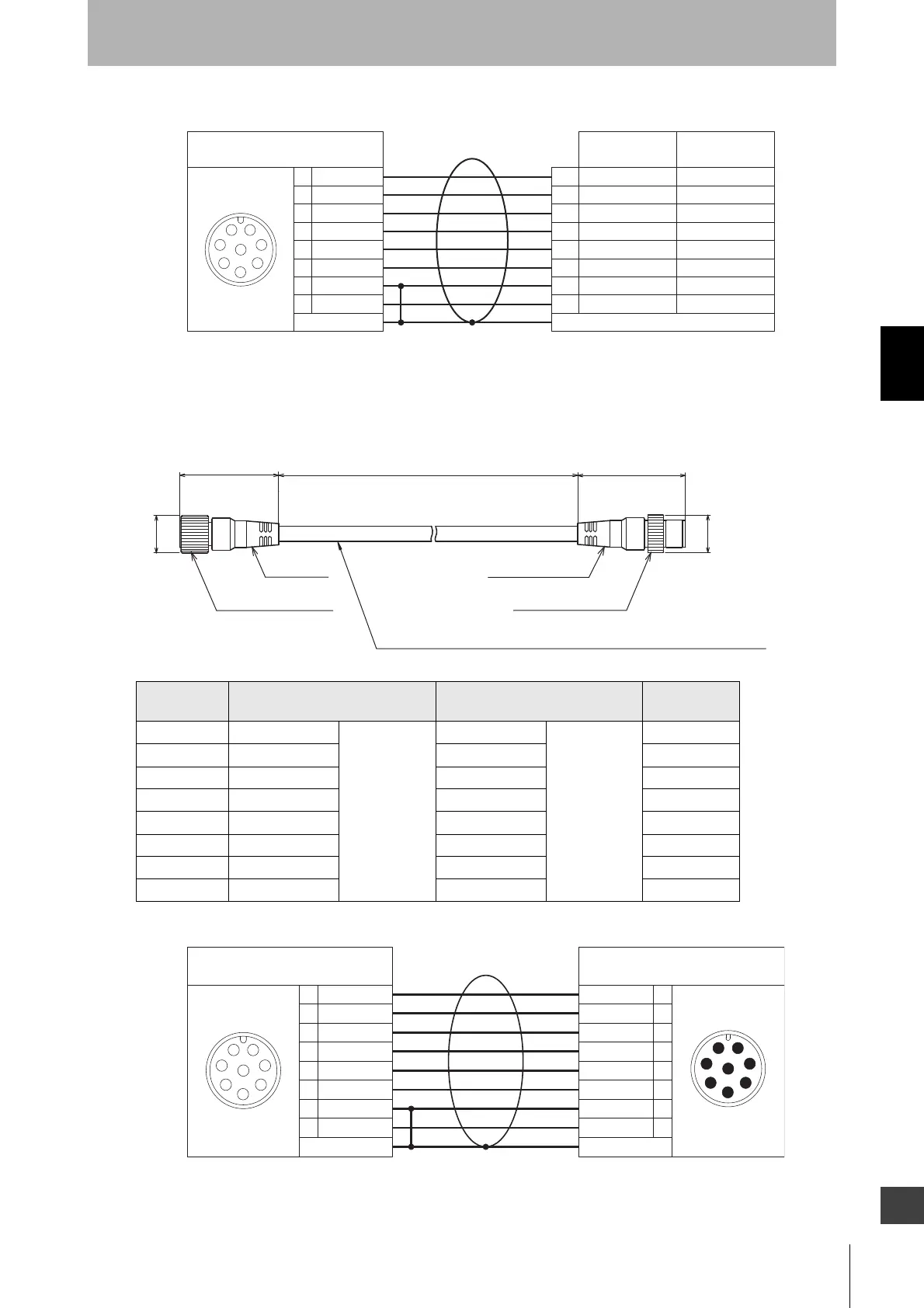
Double-ended connector cable: Cable for extension and for connection to F3SP-B1P
(F39-JDB, sold separately)
<Internal wiring diagram> (F39-JDB-L, F39-JDB-D)
Set model
name
Emitter cable Receiver cable L (mm)
F39-JDR5B F39-JDR5B-L Gray cable F39-JDR15B-D Black cable 500
F39-JD1B F39-JD1B-L F39-JD1B-D 1000
F39-JD3B F39-JD3B-L F39-JD3B-D 3000
F39-JD5B F39-JD5B-L F39-JD5B-D 5000
F39-JD7B F39-JD7B-L F39-JD7B-D 7000
F39-JD10B F39-JD10B-L F39-JD10B-D 10000
F39-JD15B F39-JD15B-L F39-JD15B-D 15000
F39-JD20B F39-JD20B-L F39-JD20B-D 20000
White
Brown
Black
Yellow
Gray
Pink
Blue
Red
1
2
3
4
5
6
7
8
Interlock select input
+24 VDC
Test input
Reset input
Communication line (+)
Communication line (-)
Communication line (+)
Communication line (-)
0V
NC
5
8
4
3
2
1
7
6
Connected to connection cable or
double-ended connector cable
Shield
Shield
Female
Safety output 2
+24 VDC
Safety output 1
Auxiliary output
0V
External device
monitoring input
White
Brown
Black
Yellow
Gray
Pink
Blue
Red
Emitter Receiver
Twisted pair wires are white and red, brown and blue, black and yellow, and gray and pink
M12 IP67 connector
Body color:
Black
Body color: Black
Insulated vinyl round cable dia. 6.6, shielded 8-wire (4-pair)
(Cross section of conductor: 0.3 mm
2
/insulator diameter: dia. 1.15 mm)
39.5
dia.15
L
43
dia.15
(Unit: mm)
M12 IP67 connector
Twisted pair wires are white and red, brown and blue, black and yellow, and gray and pink
White
Brown
Black
Yellow
Gray
Pink
Blue
Red
1
2
3
4
5
6
7
8
1
2
3
4
5
6
7
8
White
Brown
Black
Yellow
Gray
Pink
Blue
Red
5
8
4
3
2
1
7
6
5
8
6
7
1
2
3
4
Connected to connection cable or
double-ended connector cable
Connected to single-ended connector
cable, double-ended connector cable,
or controller F3SP-B1P
Shield
Shield
Female Male