26
Chapter2 Description of Functions
F3SJ-E/B
User’s Manual
System Configuration and Functions
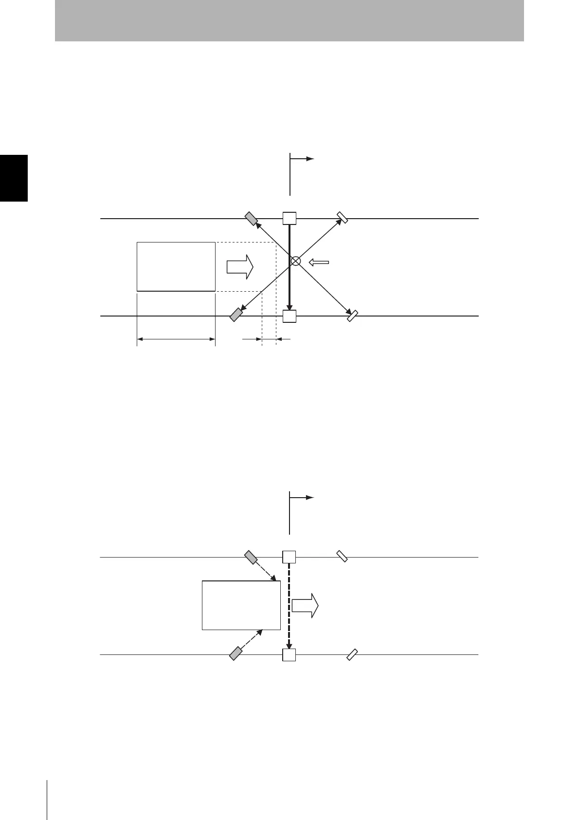
Installation example 1 of standard muting mode (Using two muting sensors)
This is an example of two retro-reflective type photoelectric sensors used as muting sensors installed
in a cross pattern.
Use two sensors when the length L of the workpieces are not constant or are insufficient.
1. Before a workpiece passes through
The output state of muting sensors A1 and B1 are both OFF (contacts A1 and B1 are open due to
muting output), and the safety function of the F3SJ-B is working.
In this example where two muting sensors are used, the crossover point of muting sensors A1 and B1
is in the hazardous zone. This configuration prevents the muting function from being enabled by a
person passing through the crossover point.
2. Muting function started working
When muting sensors A1 and B1 are turned ON in this order, the muting function is enabled. In this
state, the safety function of F3SJ-B is disabled.
Workpiece
L
F3SJ-B
F3SJ-B
d1=D1
B1
Reflector
Reflector
A1
Hazardous zone
V
The crossover point of muting sensors
A1 and B1 must be located within the
hazardous zone
L: Length of workpiece
d1: Maximum distance required for the muting sensor to keep the muting function enabled
D1: Minimum distance required for the muting sensor to keep the muting function enabled
Workpiece
F3SJ-B
F3SJ-B
Hazardous zone
B1
Reflector
Reflector
A1