31
F3SJ-E/B
User’s Manual
Chapter2 Description of Functions
System Configuration and Functions
E
To enable the muting function, D3 and d2 must satisfy formulas (3) and (4), respectively.
This distance must prevent the muting function from being enabled by a person passing through the
muting sensors. Also, install the F3SJ-B and muting sensors so that each workpiece passes through
all muting sensors before the next workpiece arrives at the first muting sensor.
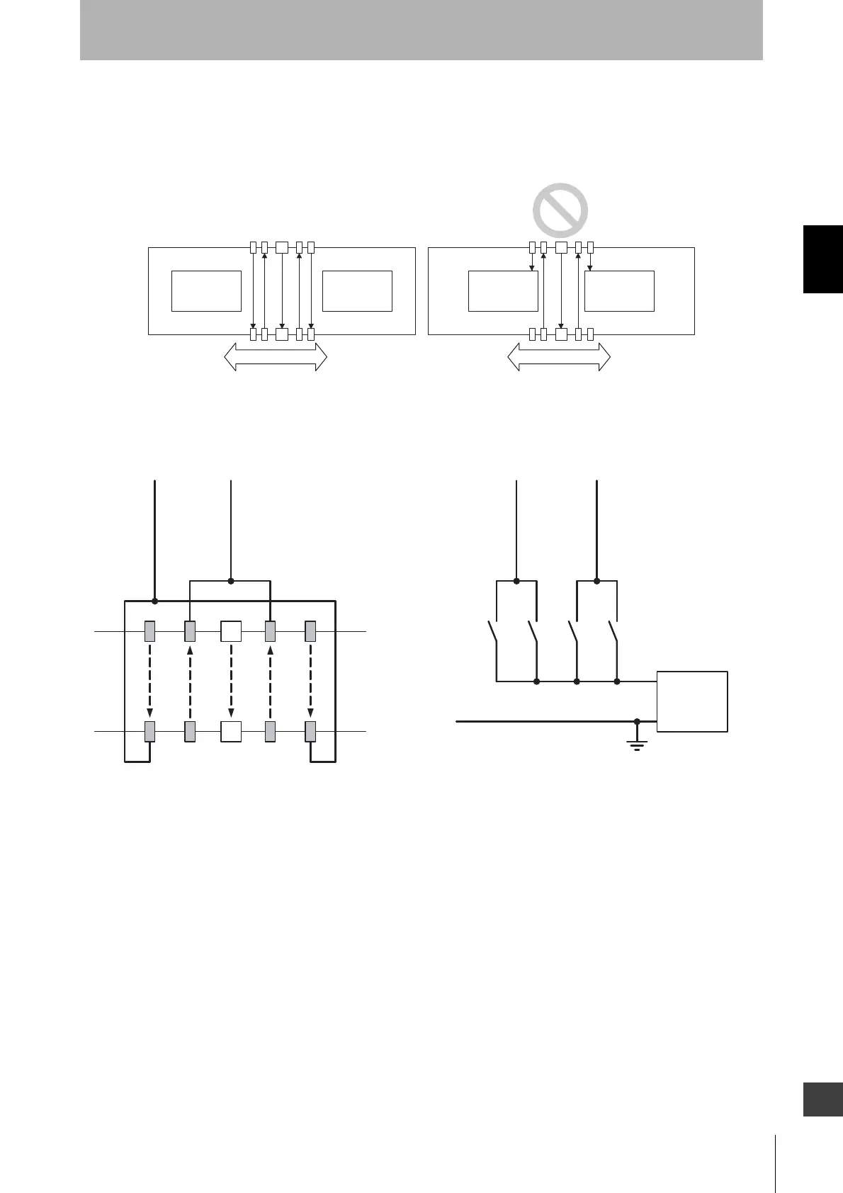
<Wiring diagram>
Moving direction
Workpiece Workpiece Workpiece Workpiece
Moving direction
+24 VDC
0 V
Power
supply
A2A1 B2B1
Muting input 1 (White)
B2
A1 A2
B1
F3SJ-B
Using a photoelectric switch as a muting sensor
* Two-wire type muting sensor cannot be used.
Using an N.O. contact type switch as a muting sensor
A1, B1, A2, B2 :
Retro-reflective
photoelectric switch
- PNP Output
- ON when Interrupted
A1, A2, B1, B2:
N.O. contact type switch
Muting input 2 (Red)
Muting input 1(White)
Muting input 2 (Red)