v
F3SJ-E/B
User’s Manual
Introduction
E
For installation
Make sure to test the operation of the F3SJ-E/B after installation to verify that the F3SJ-E/B
operates as intended. Make sure to stop the machine until the test is complete. Unintended
function settings may cause a person to go undetected, resulting in serious injury.
Make sure to install the F3SJ-E/B at the safe distance from the hazardous part of the equipment.
Otherwise, the machine may not stop before a person reaches the hazardous part, resulting in
serious injury.
Install a protective structure so that the hazardous part of a machine can only be reached by a
person that passes through the sensor's detection zone. Install the sensors so that part of the
person is always present in the detection zone when working in a machine's hazardous zones,
eliminating areas where the sensors do not reach. If a person is able step into the hazardous
zone of a machine and remain behind the F3SJ-E/B's detection zone, configure the system with
an interlock function that prevents the machine from being restarted. Failure to do so may result
in serious injury.
Install the interlock reset switch in a location that provides a clear view of the entire hazardous
zone and where it cannot be activated from within the hazardous zone.
The F3SJ-E/B cannot protect a person from a projectile exiting the hazardous zone. Install
protective cover(s) or fence(s).
Install the F3SJ-E/B so that it is not affected by a reflective surface. Failure to do so may hinder
detection, resulting in serious injury. Details on installation distance from the reflective surface,
see "Distance from Reflective Surfaces" on page 41.
When using more than one set of F3SJ-E/Bs, install them so that mutual interference does not
occur, such as by configuring series connections or using physical barriers between adjacent
sets.
Make sure that the F3SJ-E/B is securely mounted and its cables and connectors are properly
secured.
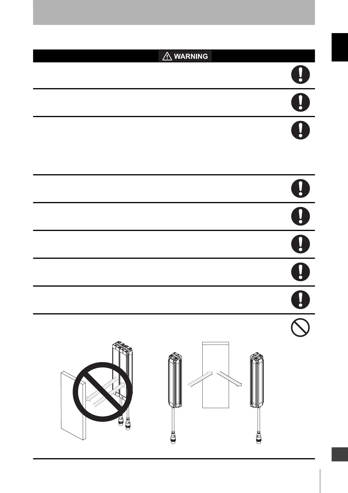
Do not use the sensor system with mirrors in a retro-reflective configuration as shown below.
Doing so may hinder detection. It is possible to use mirrors to "bend" the detection zone to a 90-
degree angle.
Reflector
Position with retro-reflection
Position with detection zone bent at 90°
Reflector