3 - 45
3 Configuration
Vision System FH/FZ5 series Hardware Setup Manual (Z366)
3-3 Camera Cable
3
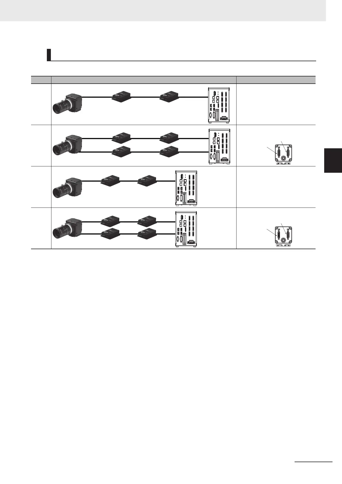
3-3-5 Cable Extension Units
Connection configuration of FH-1000 or FH-3000 Sensor Controller and Camera are the bellows.
*1. Select the Camera Cables between the Controller and Extension Unit, between the Extension Units, and between the
Extension Unit and Camera according to the connected Camera.
Different types or lengths of Camera Cables can be used for (1), (2), and (3) as well as for (4), (5), and (6). However, the
type and length of Camera Cable (1) must be the same as those of Camera Cable (4), (2) must be the same as (5), and
(3) must be the same as (6).
Connection Configuration
Connection configuration using the maximum length of Camera Cables Remarks
Con-
figura-
tion 1
Con-
figura-
tion 2
Con-
figura-
tion 3
Con-
figura-
tion 4
15 m
(1)
15 m
(4)
15 m
(2)
15 m
(5)
15 m
(3)
15 m
(6)
*1
CH1
CH2
Camera cable
connector CH2
Camera cable
connector
CH1
5 m
(1)
5 m
(2)
5 m
(3)
*1
5 m
(1)
5 m
(2)
5 m
(3)
5 m
(4)
5 m
(5)
5 m
(6)
*1
CH1
CH2
Camera cable
connector CH2
Camera cable
connector
CH1

 Loading...


