EasyManuals Logo

Omron fh series Hardware Manual

Omron fh series
254 pages
To Next Page IconTo Next Page
To Previous Page IconTo Previous Page
Page #126 background imageLoading...
Page #126 background image
3 Configuration
3 - 68
Vision System FH/FZ5 series Hardware Setup Manual (Z366)
z
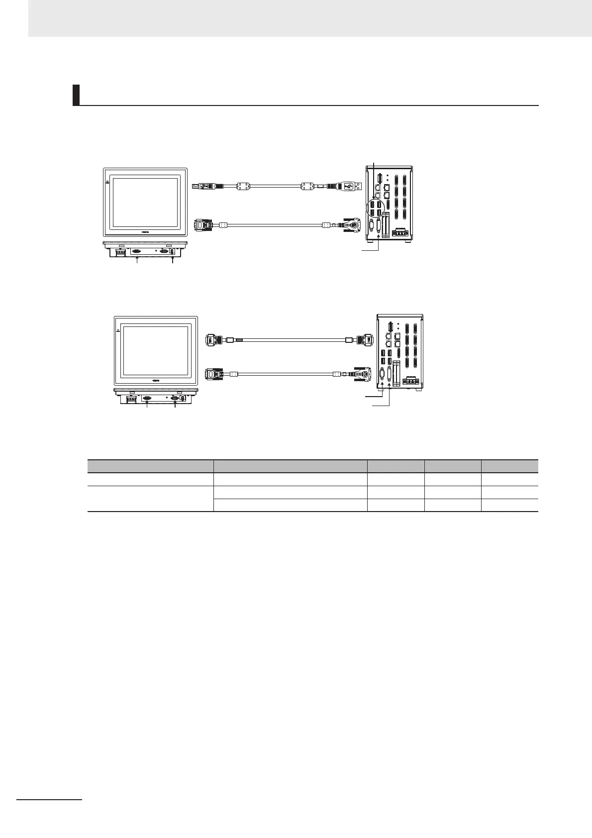
USB Connection (Cable Length Up to 5 m)
z
RS-232C Connection (Cable Length Up to 10 m)
A video signal cable and an operation signal cable are required to connect the Touch Panel Monitor.
Connection Example
Signal Cable 2 m 5 m 10 m
Video signal DVI-Analog Conversion Cable ccc
Touch panel operation signal USB Cable cc ×
RS-232C Cable ccc
Type A Type B
D-Sub
Analog RGB
DVI-A
DVI-I
USB
Touch panel cable(USB): FH-VUAB
Monitor cable: FH-VMDA
FH-MT12
FH controller
Connect a cable to an arbitrary
USB port of the FH controller.
FH controller
FH-MT12
DVI-AD-Sub
Analog RGB
DVI-I
RS-232C
Monitor cable: FH-VMDA
RS-232C
Touch panel cable(RS-232C):
XW2Z-PP-1

Table of Contents

Other manuals for Omron fh series

Questions and Answers:

Question and Answer IconNeed help?

Do you have a question about the Omron fh series and is the answer not in the manual?

Omron fh series Specifications

General IconGeneral
TypeMachine Vision System
SeriesFH Series
Power Supply24 VDC
Storage Temperature-20 to 60°C
Humidity35 to 85% RH (non-condensing)
Image SensorCMOS
Processing SpeedHigh-speed processing
ConnectivityEthernet
I/ODigital I/O
Operating SystemEmbedded OS
I/O PortsEthernet, USB

Related product manuals