5 - 21
5 Setup and Wiring
Vision System FH/FZ5 series Hardware Setup Manual (Z366)
5-3 Sensor Controller Installation
5
5-3-4 FZ5 Series
Precautions for Safe Use
Power Supply and Wiring
• Keep the power supply wires as short as possible (Max.10 m).
• Use the cables and crimping terminals with the specified dimensions.
Do not directly connect an electric wire to the terminal lock that is simply twisted.
• Recommended wire size: 1.31 to 2.63 mm
2
• Terminal screw: M4
• Crimping Terminal
Ground
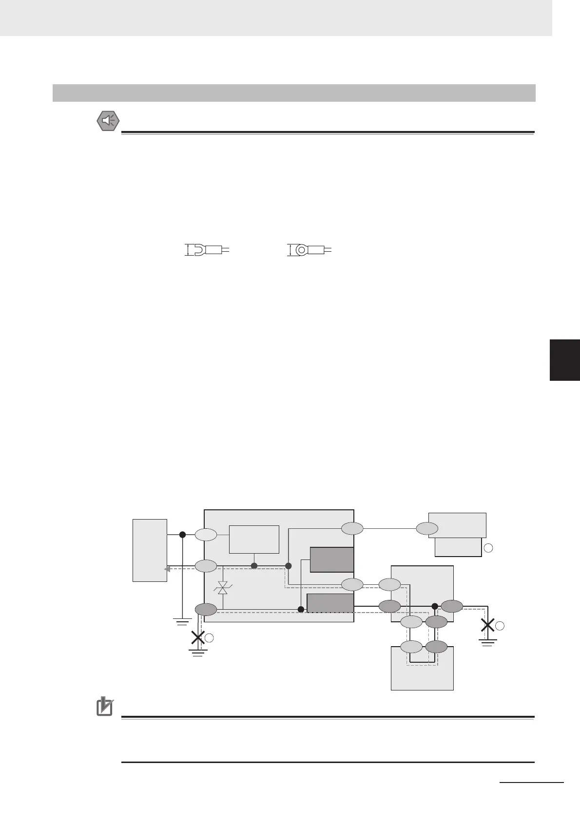
• The power supply circuit of the Sensor Controller is not insulated from the internal circuit.
• When grounding the 24 VDC power supply’s positive terminal, do not ground the controller’s
FG terminal or the PLC’s FG terminal. [c, d] Since the PC’s shell and the SG (0 V) are con-
nected inside the PC, current would run through the route shown in the figure below and
cause burnout.
• As in the case with a PC, you can safely ground the controller’s FG terminal without a prob-
lem when there is no possibility that the SG (0 V) and the FG will short-circuit. For information
about the PLC wiring, check the specifications of your PLC before wiring.
• When the connected camera to the Sensor Control comes packaged with a base, make sure
to mount with the base. [e] As the shell of the camera is the SG (0 V), it can cause short-cir-
cuiting between the SG (0 V) and the FG if a pedestal is not used.
• To avoid receiving an electric shock when grounding a positive terminal, do not touch the SG
(0 V) (camera, power supply terminal).
• Perform Class D grounding (with a grounding resistance of 100 Ω or less).
• Keep the ground line as short as possible by setting the grounding point as close as possible.
• Ground the FH Sensor Controller independently. If sharing the ground line with other devices
or connect it with a building beam, the controller might be adversely effected.
Precautions for Correct Use
The LCD panel used for the LCD-integrated type has been made using precision technology,
and sometimes a few pixels are missing in the panel. This is due to the structure of the LCD
panel, and is not a malfunction.
5-3-4 FZ5 Series
8.5 mm max. 8.5 mm max.
1
2
3
SG (0 V)
0V
SG SG
24 V
SG
SG
FG
FG FG
RS-232C
RS-232C
SG
SG
SG FG
FG
PLC
FG
Power
supply
Controller
Camera cable
SG (0 V)
Camera
Mounting Spacer
(insulator)
Power supply
circuit
PC
Shell
Parallel I/O
connectorʼs
shell
RS-232C
connector
ʼ
s shell
SG: Signal Ground
FG: Frame Ground

 Loading...


