5 Setup and Wiring
5 - 40
Vision System FH/FZ5 series Hardware Setup Manual (Z366)
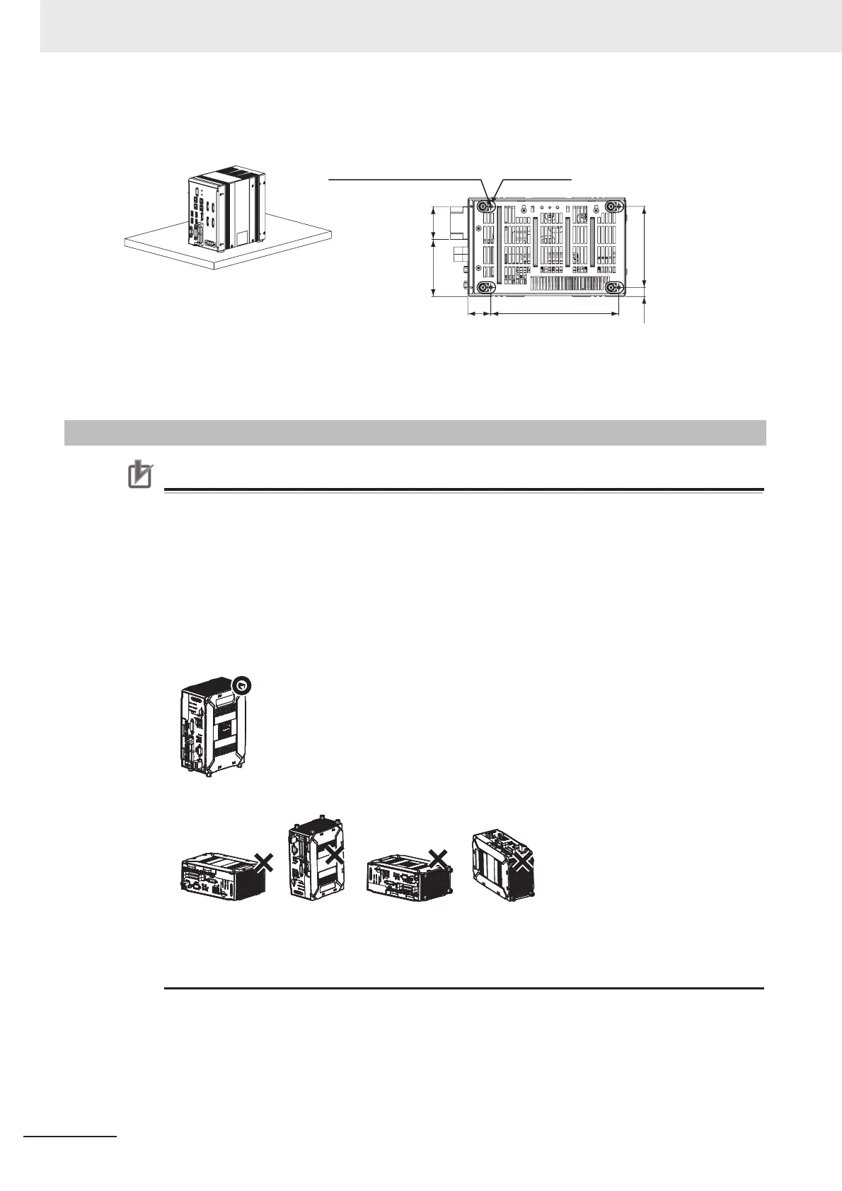
Bottom Mounting
Precautions for Correct Use
Ambient Temperature
• Install and store the product in a location that meets the following conditions:
• Surrounding temperature of 0 to 55
°C (-25 to +70°C in storage)
• Relative humidity of between 10 to 90
% RH
Orientation of Product
• For good heat dissipation, install the product only in the position shown below so as not to
block the ventilation holes.
• Do not install the product in the following positions.
• To keep proper air flow, keep the top of the FH Sensor Controller 50 mm or more apart from
other devices. Install the FH Sensor Controller with a clearance of 30 mm on the right and left
side, and 15 mm for rear planes. The clearance is required for installing multiple units
side-by-side. For the back mounting, the back-side clearance of 15 mm is nor required.
5-8-3 FH-L Series
38.1
26.7
148.5
10.5
94
66.2
4-M3 depth 4.5 (mounting screw hole) Insulating leg: 4
• Bottom
(Unit: mm)
* Do not remove the Insulating leg. Fix the Insulating leg to secure the
ventilation path.
* Recommended tightening torque: 0.54 N•m to 0.6 N•m
* The tolerance is ±0.2 mm.

 Loading...


