5 - 39
5 Setup and Wiring
Vision System FH/FZ5 series Hardware Setup Manual (Z366)
5-8 Installation in a Control Panel
5
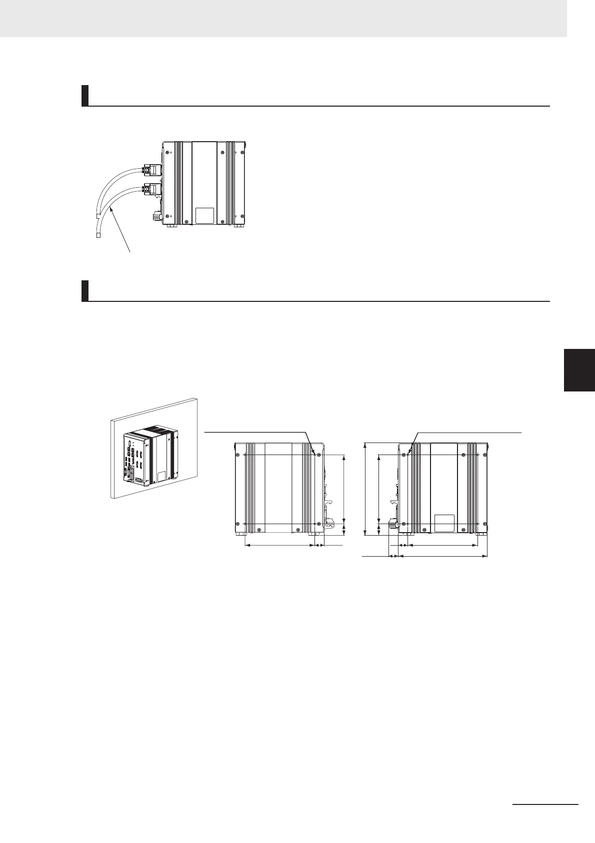
5-8-2 FH-1000/FH-3000 Series
When you connect the cable to the Sensor Controller, secure the minimum bending radius of the cable
or cable connector.
• Make sure to tighten all installation screws securely.
• To keep proper air flow, keep the top of the FH Sensor Controller 50 mm or more apart from other
devices. Install the FH Sensor Controller with a clearance of 30 mm on the right and left side, and 15
mm for rear planes. The clearance is required for installing multiple units side-by-side.
Side Mounting
Accessibility for Operation and Maintenance
Installation in a Control Panel
19.5
143
24
141
4-M4 depth 4.5 (mounting screw hole)
19.2
143
182.5
24
141
190
20.1
4-M4 depth 4.5 (mounting screw hole)
(Unit: mm)
• Left side • Right side
* Recommended tightening torque: 1.2 N•m to 1.3 N•m
* The tolerance is ±0.2 mm.

 Loading...


