EasyManuals Logo

Omron fh series Hardware Manual

Omron fh series
254 pages
To Next Page IconTo Next Page
To Previous Page IconTo Previous Page
Page #114 background imageLoading...
Page #114 background image
3 Configuration
3 - 56
Vision System FH/FZ5 series Hardware Setup Manual (Z366)
Select lens appropriate for the camera.
For more details, refer to Vision Accessory Catalog (Cat. No. Q198).
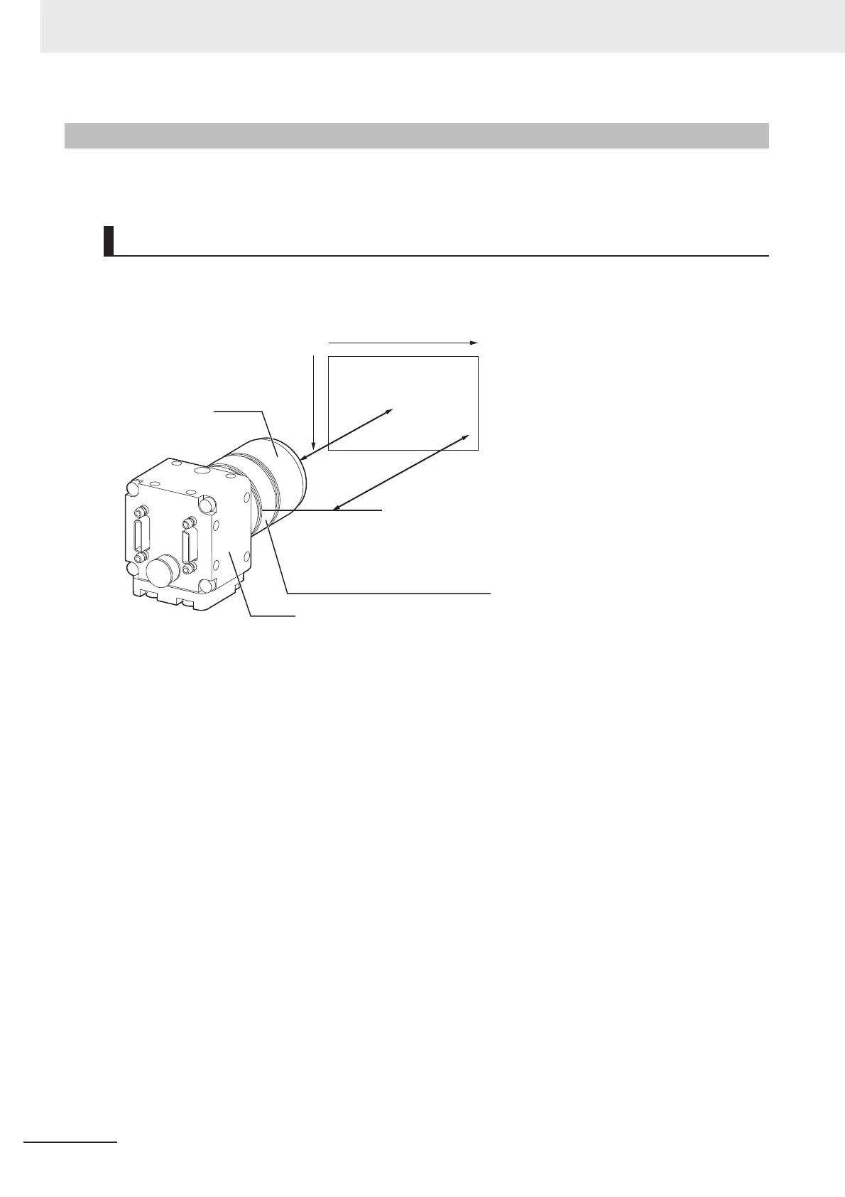
The X axis of the optical chart shows the field of vision (mm)
*1
,
The Y axis of the optical chart shows the camera installation distance (mm) or WD
*2
.
*1. The lengths of the fields of vision given in the optical charts are the lengths of the Y axis.
*2. The vertical axis represents WD for small cameras.
3-4-9 Meaning of Optical Chart
How-to View the Optical Chart
y
x
Lens
Field of vision
(mm)
Camera distance
(mm)
Camera
Extension Tube thickness: t(mm)
WD
(mm)
WD
(mm)

Table of Contents

Other manuals for Omron fh series

Questions and Answers:

Question and Answer IconNeed help?

Do you have a question about the Omron fh series and is the answer not in the manual?

Omron fh series Specifications

General IconGeneral
TypeMachine Vision System
SeriesFH Series
Power Supply24 VDC
Storage Temperature-20 to 60°C
Humidity35 to 85% RH (non-condensing)
Image SensorCMOS
Processing SpeedHigh-speed processing
ConnectivityEthernet
I/ODigital I/O
Operating SystemEmbedded OS
I/O PortsEthernet, USB

Related product manuals