6 I/O Interface
6 - 54
Vision System FH/FZ5 series Hardware Setup Manual (Z366)
• Connect the LAN cable with a straight or cross cable.
• Use an STP (shielded twisted-pair) cable of category 5, 5e, or higher.
• Electrical specifications: Conforming to IEEE 802.3 standards. Use RJ45 8-pin Modular Connector
(conforming to ISO 8877).
• When selecting a connector, confirm that it is applicable to the cable that will be used. Confirm the
following items: Conductor size, conductor type (solid wire or twisted wire), number of twisted pairs (2
or 4), outer diameter, etc.
10Base-T and 100Base-TX
Connect the shield to connector hoods as described below.
• Connect the shields at both ends of the cables to connector hoods. Connect only the shield at the
end of the cable on the Ethernet switch side to the connector hood.
6-4-3 FZ5 Series
Cable
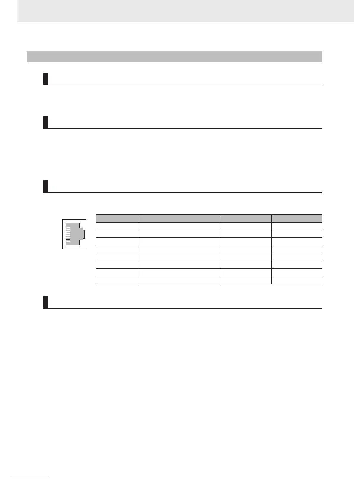
I/O Connector
Pin Layout
Connector pin Signal name Abbr. Signal direction
1 Transmission data + TD + Output
2 Transmission data - TD - Output
3 Reception data + RD + Input
4 Not used. --- ---
5 Not used. --- ---
6 Reception data - RD - Input
7 Not used. --- ---
8 Not used. --- ---
Wire

 Loading...


