5 Setup and Wiring
5 - 20
Vision System FH/FZ5 series Hardware Setup Manual (Z366)
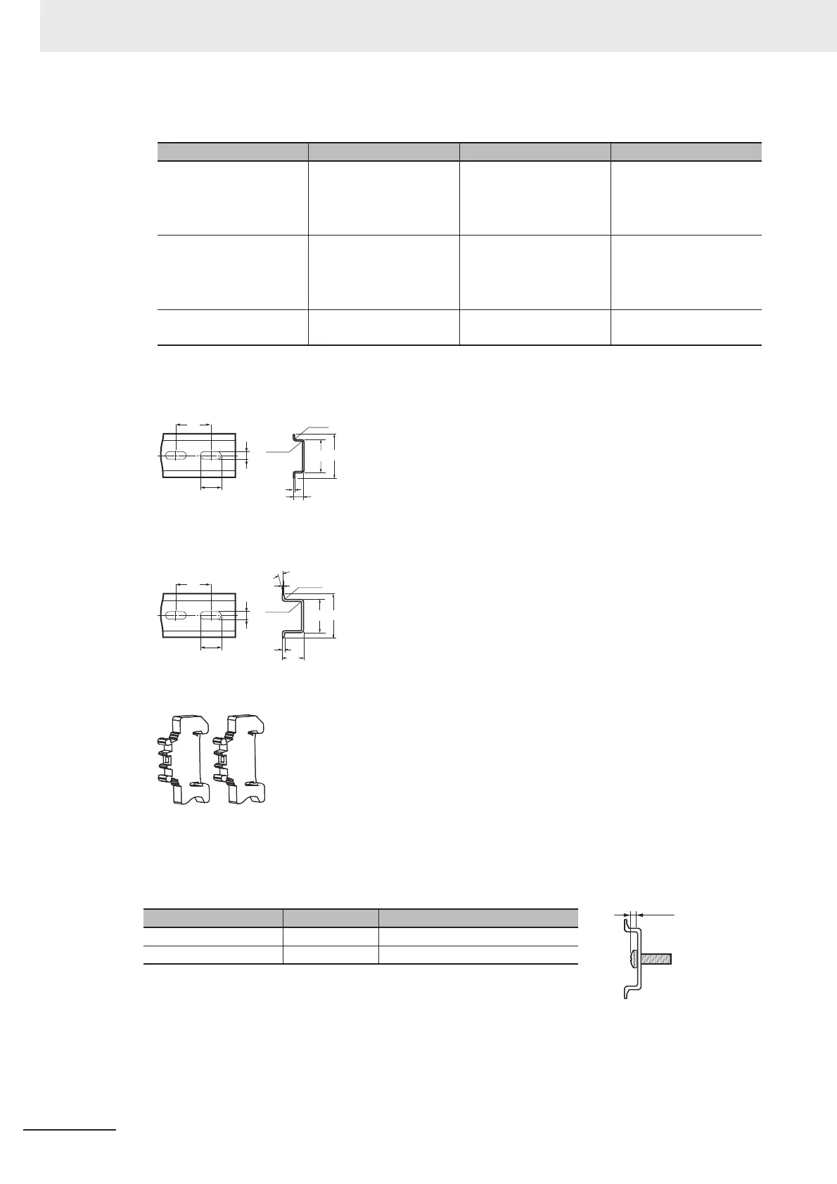
• The following items are recommended for mounting DIN rail.
• DIN rail Dimensions
NS 35/7,5 PERF
NS 35/15 PERF
•End plate
For screw or washer, refer to the followings.
(a): Length between head of screw and fastening surface.
Name Model Manufacturer Note
DIN35 mm rail NS 35/ 7,5 PERF PHOENIX CONTACT
• Length:
75.5/95.5/115.5/200 cm
• Material: Iron
• Surface: Conductive
End plate NS 35/ 15 PERF PHOENIX CONTACT
• Length:
75.5/95.5/115.5/200 cm
• Material: Iron
• Surface: Conductive
End plate CLIPFIX 35 PHOENIX CONTACT Need 2 pieces each
Sensor Controller.
Model
Screw Diameter
(a)
NS 35/ 7,5 PERF M6 4.6 mm max.
NS 35/ 15 PERF M6 10 mm max.
1.5
0.8
15
35
27
R1.25
15°
R1.25
6.2
15
25
(a)

 Loading...


