3 - 69
3 Configuration
Vision System FH/FZ5 series Hardware Setup Manual (Z366)
3-6 Touch Panel Monitor and Cable
3
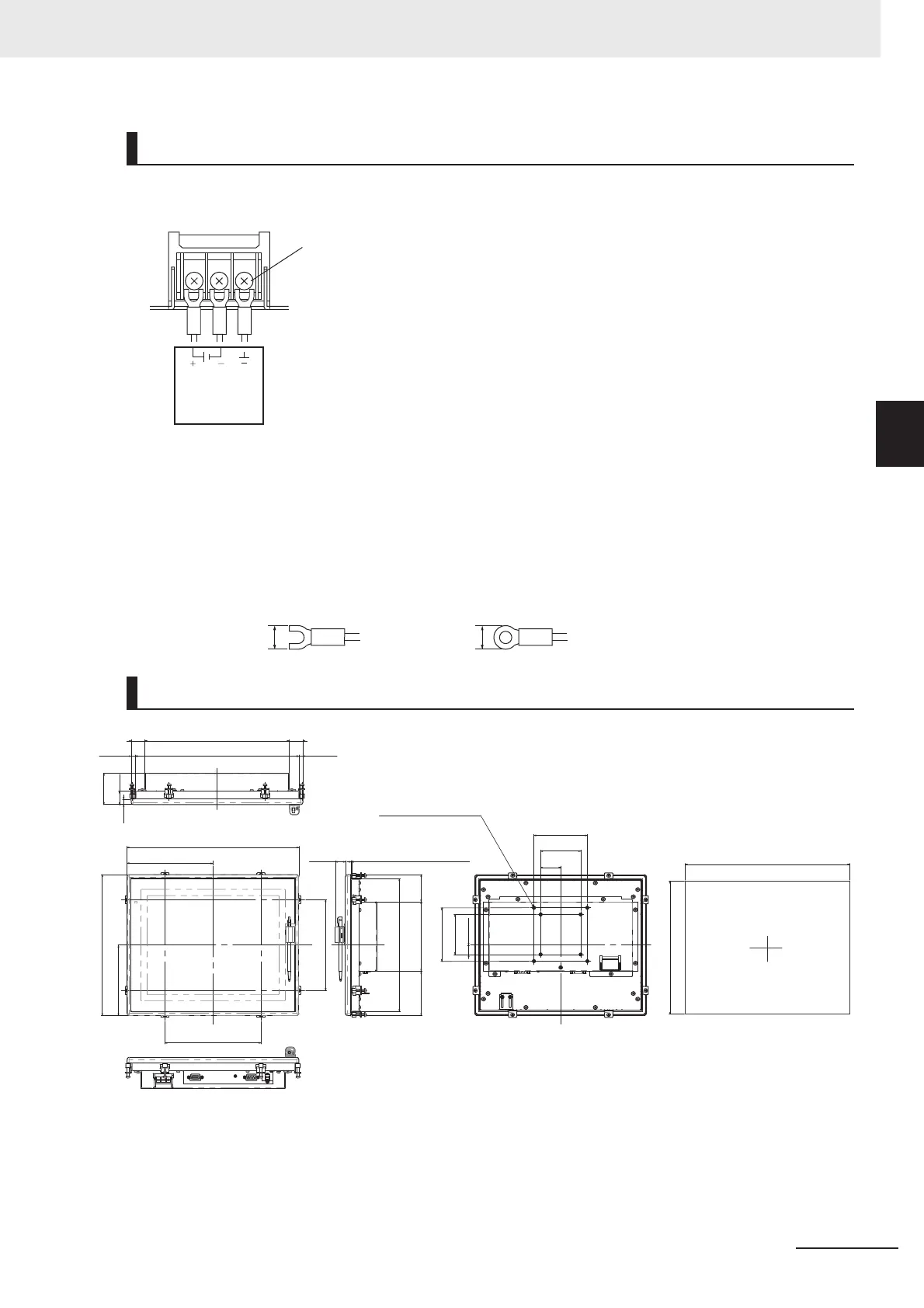
The power connection for the Touch Panel Monitor is on the back side of the Monitor.
Connect the 24 VDC power source.
• Keep the power supply wires as short as possible. (Max.2 m)
• If UL's certification is required, use a UL class II power supply.
• Use the cables and crimping terminals with the specified dimensions.
Do not directly connect an electric wire that is simply twisted to the terminal block.
• Recommended wire size: AWG 13 to 22 (0.326 to 2.62 mm
2
)
• Terminal screw: M4 (Tightening torque: 1.0 N•m)
• Crimping Terminal
Note 1. Panel thickness: 1.6 to 4.8 mm
2. No burr allowed
Wiring
Dimensions
M4
Power supply
24 VDC
24 VDC
Recommended model
by OMRON:
S8VS-03024
307
249
322
264
161
132
180
170
10
25
58.5
270
26 26
306.52
7.74
7.74
130
83
(51)
Mounting plate
thickness 1.6-4.8
(19)
248.52
17.5
75
100
37.5
75
100
8-M4 Effective
screw length6
Panel cutout dimensions
+1
0
+1
0

 Loading...


