EasyManuals Logo

Omron fh series Hardware Manual

Omron fh series
254 pages
To Next Page IconTo Next Page
To Previous Page IconTo Previous Page
Page #214 background imageLoading...
Page #214 background image
6 I/O Interface
6 - 22
Vision System FH/FZ5 series Hardware Setup Manual (Z366)
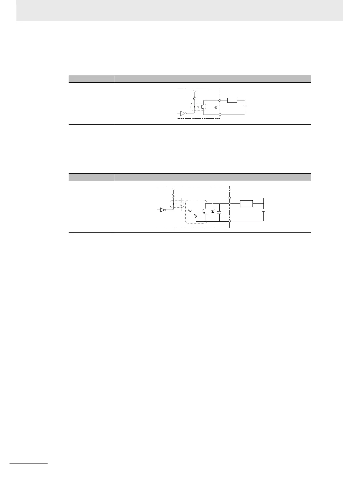
c) [Output]
Applicable signals:
BUSY0, RUN/BUSY1, OR0 to 1, GATE0 to 1, ERROR, DO0 to 15, READY0 to 1
d) [Output]
Applicable signals:
STGOUT0 to 3
When STGOUT0 to 3 are used, connect the terminal.
Item Specifications
Internal circuit
diagram
Item Specifications
Internal circuit
diagram
Each output terminal
Load
COM OUT
+
COM OUT
COM IN
Each output
terminal
Load
+

Table of Contents

Other manuals for Omron fh series

Questions and Answers:

Question and Answer IconNeed help?

Do you have a question about the Omron fh series and is the answer not in the manual?

Omron fh series Specifications

General IconGeneral
TypeMachine Vision System
SeriesFH Series
Power Supply24 VDC
Storage Temperature-20 to 60°C
Humidity35 to 85% RH (non-condensing)
Image SensorCMOS
Processing SpeedHigh-speed processing
ConnectivityEthernet
I/ODigital I/O
Operating SystemEmbedded OS
I/O PortsEthernet, USB

Related product manuals