6 I/O Interface
6 - 24
Vision System FH/FZ5 series Hardware Setup Manual (Z366)
[Input]
Applicable signals/
STEP0/ENCTRIG_Z0, STEP1/ENCTRIG_Z1, ENCTRIG_A0 to 1, ENCTRIG_B0 to 1
[Output]
Applicable signals:
BUSY0, RUN/BUSY1, OR0 to 1, GATE0 to 1, ERROR, DO0 to 15, READY0 to 1
[Output]
Applicable signals:
STGOUT0 to 3
When STGOUT0 to 3 are used, connect the COMIN terminal.
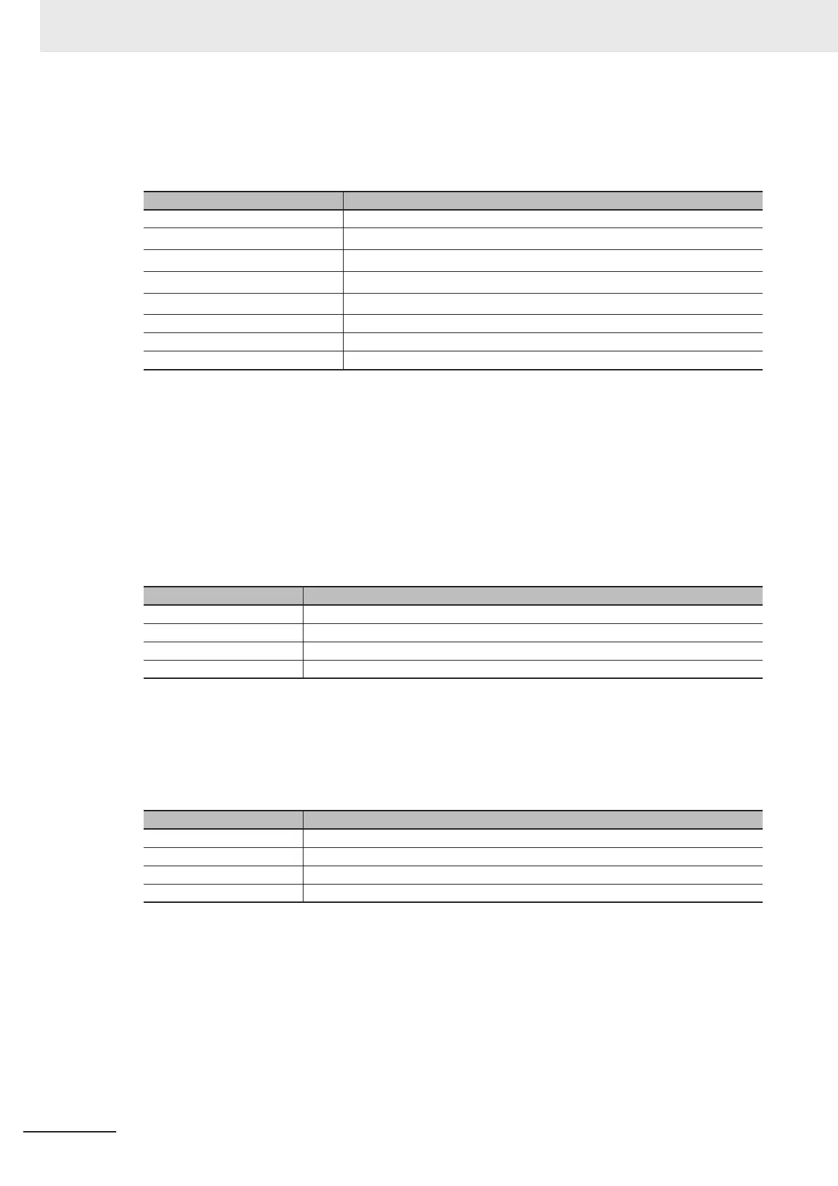
Item Specifications
Input voltage 12 to 24 VDC ±10%
ON current
*1
*1. ON current and ON voltage:
Those mean the current or voltage to turn ON from OFF. The ON voltage value is the potential difference
between COMIN and each input terminal.
5 mA min.
ON voltage
*1
8.8 V min.
OFF current
*2
*2. OFF current and OFF voltage:
Those mean the current or voltage to turn OFF from ON. The OFF voltage value is the potential difference
between COMIN and each input terminal.
0.5 mA max.
OFF voltage
*2
0.8 V max.
ON delay 0.1 ms max.
OFF delay 0.1 ms max.
Maximum frequency response 0.95 KHz
Item Specifications
Output voltage 12 to 24 VDC ±10%
Load current 45 mA max.
ON residual voltage 2 V max.
OFF leakage current 0.2 mA max.
Item Specifications
Output voltage 12 to 24 VDC ±10%
Load current 45 mA max.
ON residual voltage 2 V max.
OFF leakage current 0.2 mA max.

 Loading...


