6 - 27
6 I/O Interface
Vision System FH/FZ5 series Hardware Setup Manual (Z366)
6-1 Parallel Interface
6
6-1-5 PNP Input/Output for FZ5 Series
• Handling the output common terminals
COMOUT1: STGOUT0 to 3, RUN/BUSY1, ERROR, BUSY0, OR0 to 1, GATE0 to 1
COMOUT2: READY0 to 1, DO0 to 7
COMOUT3: DO8 to 15
*1. This is a signal that is used when the strobe device is connected to the Controller.
*2. This signal is only available in the Random trigger mode.
*3. ON while the layout turned on output setting is displayed/ON during processing
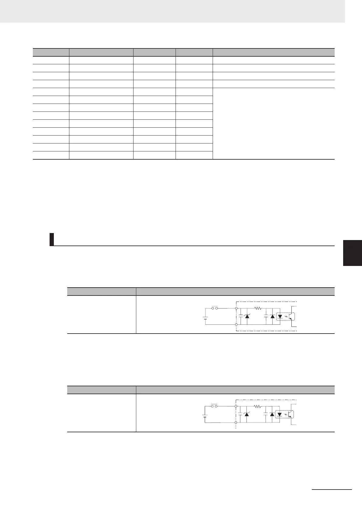
[Input]
Applicable signals:
RESET, DI0 to DI7, DSA0, DSA1
[Input]
Applicable signals:
STEP0/ENCTRIG_Z0, STEP1/ENCTRIG_Z1, ENCTRIG_A0 to 1, ENCTRIG_B0 to 1
B13 BUSY0 White ŶŶŶ ON during processing
B14 GATE0 Yellow ŶŶŶ ON for the set output time
B15 OR0 Pink ŶŶŶ Overall judgment result
B16 READY0 Orange ŶŶŶŶ ON when image input is allowed
B17 DO0 Gray ŶŶŶŶ Data output
B18 DO2 White ŶŶŶŶ
B19 DO4 Yellow ŶŶŶŶ
B20 DO6 Pink ŶŶŶŶ
B21 DO8 Orange
ŶŶŶŶŶŶŶŶŶŶŶŶŶŶŶŶŶŶŶŶŶŶŶŶŶŶŶŶŶŶŶŶŶŶŶŶŶŶŶŶ
B22 DO10 Gray
ŶŶŶŶŶŶŶŶŶŶŶŶŶŶŶŶŶŶŶŶŶŶŶŶŶŶŶŶŶŶŶŶŶŶŶŶŶŶŶŶ
B23 DO12 White
ŶŶŶŶŶŶŶŶŶŶŶŶŶŶŶŶŶŶŶŶŶŶŶŶŶŶŶŶŶŶŶŶŶŶŶŶŶŶŶŶ
B24 DO14 Yellow
ŶŶŶŶŶŶŶŶŶŶŶŶŶŶŶŶŶŶŶŶŶŶŶŶŶŶŶŶŶŶŶŶŶŶŶŶŶŶŶŶ
B25 DO15 Pink
ŶŶŶŶŶŶŶŶŶŶŶŶŶŶŶŶŶŶŶŶŶŶŶŶŶŶŶŶŶŶŶŶŶŶŶŶŶŶŶŶ
Internal Specifications for Parallel Interface
Item Specifications
Internal circuit diagram
Item Specifications
Internal circuit diagram
No. Signal name Wire color Mark (red) Function
Each input terminal
COM IN
+
+
Each input terminal
COM IN

 Loading...


