6 - 45
6 I/O Interface
Vision System FH/FZ5 series Hardware Setup Manual (Z366)
6-2 Encoder Interface
6
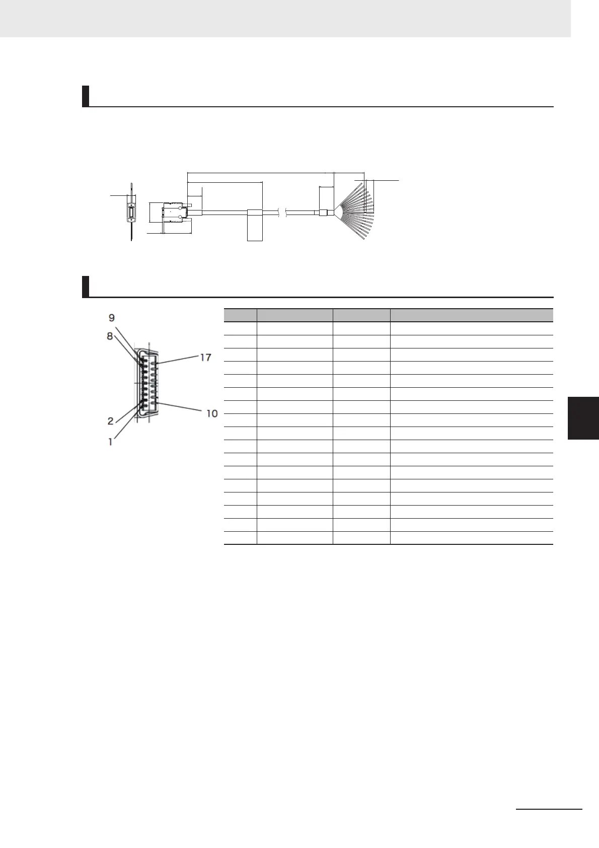
Use the following Encoder cable: FH-VR 1.5 M (1.5 m, Min Min. bending radius: 65 mm).
Encoder Cable
*1. Cable is available in 1.5 m.
Cable. I/O Connector and Terminal Block
Pin Layout
No Signal name Color Remarks
1 ENC0 A+ Black Signal: Ch1 A-Phase(+)
2 ENC0 A- Black/Red Signal: Ch1 A-Phase(-)
3 ENC0 VDD Brown Power: Power supply for Ch1 (5 VDC)
4 ENC0 B+ White Signal: Ch1 B-Phase(+)
5 ENC0 B- White/Red Signal: Ch1 B-Phase(-)
6 ENC0 GND Blue Power: Signal ground for Ch1 (0 V)
7 ENC0 Z+ Orange Signal: Ch1 Z-Phase(+)
8 ENC0 Z- Orange/Red Signal: Ch1 Z-Phase(-)
9 NC --- ---
10 ENC1 A+ Purple Signal: Ch2 A-Phase(+)
11 ENC1 A- Purple/Red Signal: Ch2 A-Phase(-)
12 ENC1 VDD Brown/Red Power: Power supply for Ch2 (5 VDC)
13 ENC1 B+ Pink Signal: Ch2 B-Phase(+)
14 ENC1 B- Pink/Red Signal: Ch2 B-Phase(-)
15 ENC1 GND Blue/Red Power: Signal ground for Ch2 (0 V)
16 ENC1 Z+ Yellow Signal: Ch2 Z-Phase(+)
17 ENC1 Z- Yellow/Red Signal: Ch2 Z-Phase(-)
FH-VR
L1
*1
90±5
3
10±2
20
20
100
26
37.22.2
11.7

 Loading...


