2. Functions, Wiring and Settings
68
G9SX
USER'S GUIDE
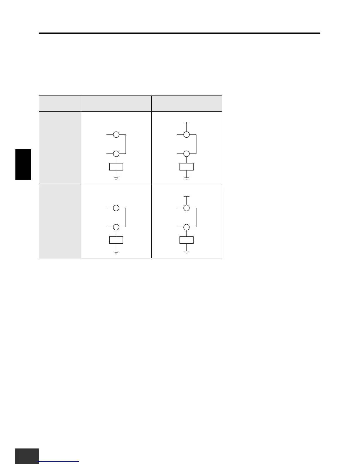
2-9 External Indicator Fault Diagnosis
Diagnostic checks of external indicators connected to the G9SX-GS's external indicator outputs UA and UB can be
switched with Y3 and Y4, respectively.
Note: 1. If there is no indicator connected to external indicator output UA, connect Y3 to 24 V. If there is no indicator connected to external indicator output
UB, connect Y4 to 24 V. If they are not connected to 24 V, the G9SX-GS will detect an error.
2. Diagnostic checks cannot be made for LED indicators. Disable the diagnostic check if using LED indicators.
External indicator
output
Diagnostic check enabled Diagnostic check disabled
UA
UB