2. Logical AND Connections
The logical AND connection is used to build logic between multiple safety inputs and safety outputs. This technology
is unique to the G9SX Series.
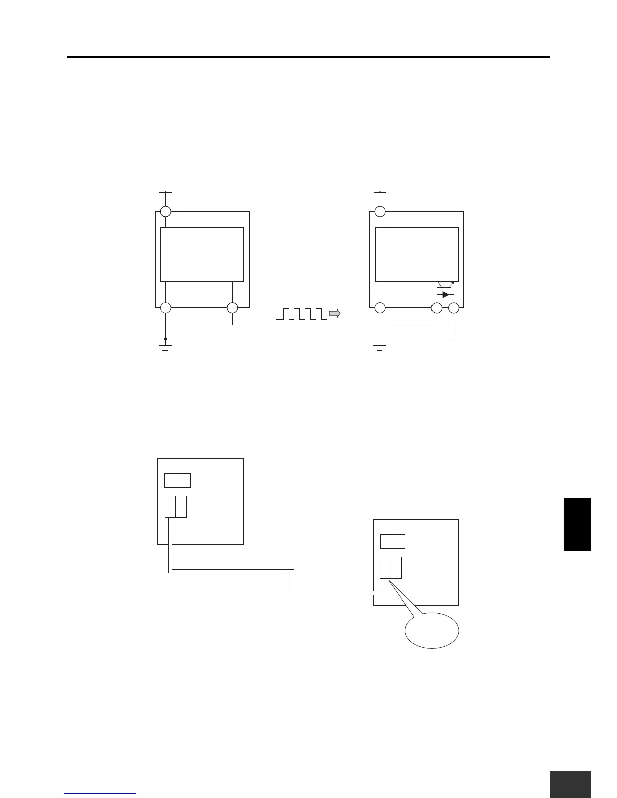
■ Logical AND Connection Signals
Pulse signals are used in the G9SX logical AND connection and dynamic processing is used to monitor the signals.
Information on safety between Units is passed by these pulse signals, which are also used to detect faults in the
connection and short circuits.
For this reason, up to safety category 4 can be achieved without redundant logical AND connection signal lines.
■ Insulation
The logical AND connection input section of the G9SX is insulated. Therefore, even when the G9SX logical AND
connection cable is configured across multiple devices, it is not necessary to use a shared power source.