1-2 Non-contact Door Switch Controller
Power input
Note: Power consumption of loads not included.
Inputs
Note: 1. Only applies to the G9SX-NSA222-T03-@. Refers to input other than that from the Non-contact Door Switch.
2. Provide a current equal to or higher than that of the minimum applicable load of the connected input control device.
Outputs
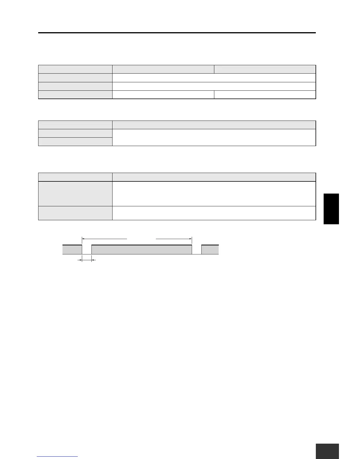
Note: 1. While safety outputs are in the ON state, the following signal sequence is output continuously for diagnosis.
When using the safety outputs as input signals to control devices (i.e. Programmable Controllers), consider the OFF pulse shown below.
2. The following derating is required when Units are mounted side-by-side.
G9SX-NS202-@/G9SX-NSA222-T03-@: 0.4 A DC max. load current
3. Apply the following rated load conditions for inductive loads.
IEC/EN 60947-5-1 DC13: 0.8 A
UL508 Pilot Duty: 0.5 A
Item Model G9SX-NS202-@ G9SX-NSA222-T03-@
Rated supply voltage 24 VDC
Operating voltage range −15% to 10% of rated supply voltage
Rated power consumption (See note.)
3 W max. 4 W max.
Item Model G9SX-NS202-@/G9SX-NSA222-T03-@
Safety input (See note 1.)
Operating voltage: 20.4 VDC to 26.4 VDC, internal impedance: approx. 2.8kΩ (See note 2.)
Feedback/reset input
Item Model G9SX-NS202-@/G9SX-NSA222-T03-@
Instantaneous safety output
(See note 1.)
OFF-delayed safety output
(See note 1.)
P channel MOS FET transistor output
Load current: 0.8 A DC max. (See note 2 and 3.)
Auxiliary output
PNP transistor output
Load current: 100 mA max.