7 - 55
7 Digital I/O Slave Unit
GX-series EtherCAT Slave Unit User’s Manual
7-4 Specifications for Each Slave Unit
7
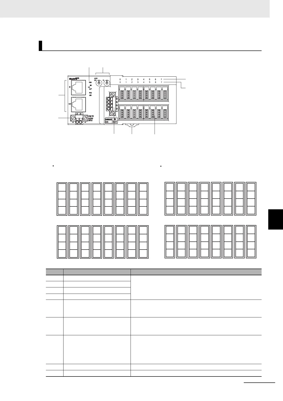
7-4-10 e-CON Connector Type 8-point Input and 8-point Output Slave Unit
GX-MD1618/MD1628
Terminal arrangement diagram
Names and functions
No. Name Function
(1) Communications connectors
Refer to "6-3 Specifications of Common Areas" in Page 6 - 4.
(2) Unit power supply connector
(3) Status indicators
(4) Node Address setting Switches
(5) Input indicators (0 to 7)
Indicates the state of an input contact (ON/OFF).
Not lit: Contact OFF (input OFF state)
Lit in yellow: Contact ON (input ON state)
(6) Output indicators (0 to 7)
Indicates the state of an output contact (ON/OFF).
Not lit: Contact OFF (output OFF state)
Lit in yellow: Contact ON (output ON state)
(7) I/O connectors (0 to 15)
Connects an external device.
<Top side>
For input device
<Bottom side>
For output device
(8) I/O power supply connector Supplies the I/O power. (For output device)
(9) DIN track mounting hook Fixes a Slave Unit to a DIN track.
(5)
(1)
(7)
(2)
(3)
(4)
(9)
(8)
(6)
Top side: input Bottom side: output
GX-MD1618
●
01234567
1
2
3
4
NC
NC NC NC
NC
NC NC NC
8 9 10 11 12 13 14 15
1
2
3
4
V
V VVVVVV
NC
NC NC NC
NC
NC NC NC
GGGG
G
GGG
OUT
0
OUT
1
OUT
2
OUT
3
OUT
4
OUT
5
OUT
6
OUT
7
V1
V1 V1 V1
V1
V1 V1 V1
G0 G1 G2 G3
G4
G5 G6 G7
IN0 IN1 IN2 IN3 IN4 IN5 IN6 IN7
01234567
1
2
3
4
NC
NC NC NC
NC
NC NC NC
8 9 10 11 12 13 14 15
1
2
3
4
V
VVVVVVV
NC
NC NC NC
NC
NC NC NC
GGGG
G
GGG
OUT
0
OUT
1
OUT
2
OUT
3
OUT
4
OUT
5
OUT
6
OUT
7
V0
V1 V2 V3
V4
V5 V6 V7
G1 G1 G1 G1
G1
G1 G1 G1
IN0 IN1 IN2 IN3 IN4 IN5 IN6 IN7
Top side: input Bottom side: output
GX-MD1628

 Loading...