8 Analog I/O Slave Unit
8 - 20
GX-series EtherCAT Slave Unit User’s Manual
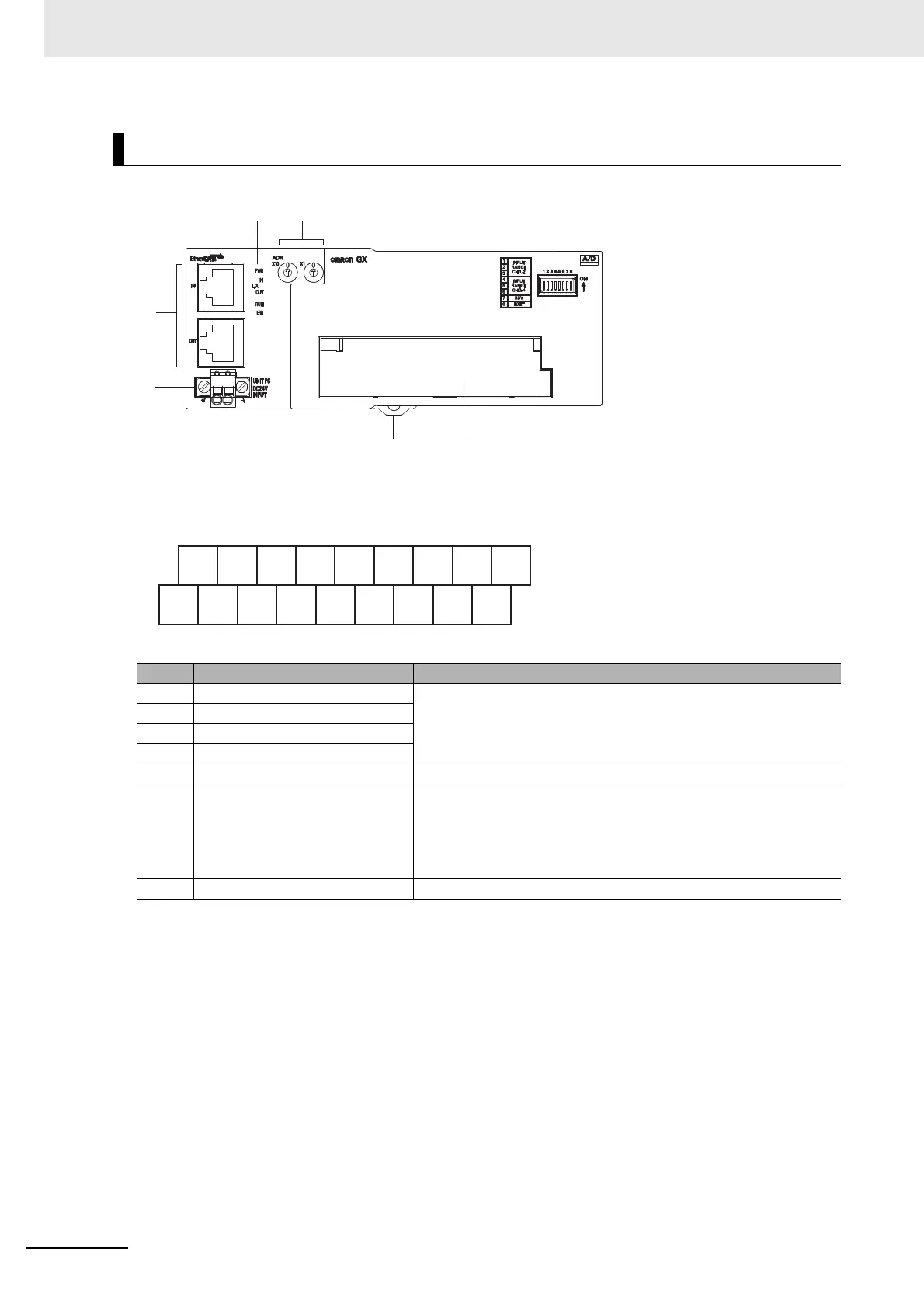
Terminal arrangement diagram
Names and functions
No. Name Function
(1) Communications connectors
Refer to "Specifications of Common Areas" in Page 6 - 4.
(2) Unit power supply connector
(3) Status indicators
(4) Node Address setting Switches
(5) Input range setting Switches DIP switches for setting input range (Refer to the following section.)
(6) Terminal block
Terminal block for analog input signals
V1 to V4: Voltage input terminals
I1 to I4: Current input terminals
AG: Analog GND
NC: Not used
(7) DIN track mounting hook Fixes a Slave Unit to a DIN track.
V1
+
I1
+
V2
+
I2
+
V3
+
I3
+
V4
+
I4
+
NC
AG
V1
−
AG
V2
−
AG
V3
−
AG
V4
−
NC

 Loading...