8 Analog I/O Slave Unit
8 - 24
GX-series EtherCAT Slave Unit User’s Manual
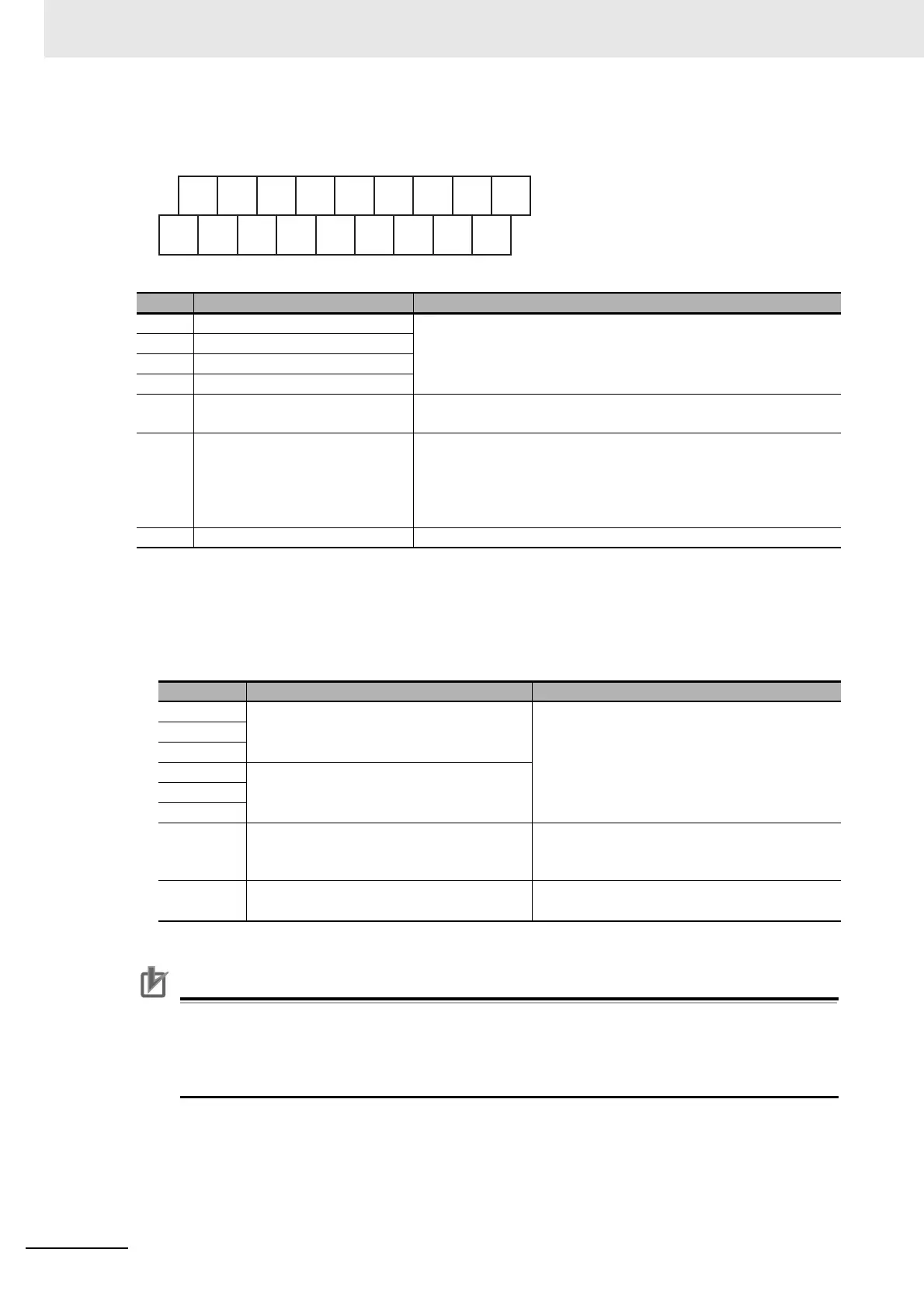
Terminal arrangement diagram
• Output range setting switches
Set output range by combination of individual DIP switches.
To enable settings of these switches, it is necessary to turn Pin8 (output range setting method) ON
in advance.
Precautions for Correct Use
• Pin7 must be used in the OFF state.
• To set a range using these switches, make sure to turn Pin8 ON. If it is turned OFF, the DIP
switch settings will not be reflected.
• The settings of this switch are read only once when the power is turned ON.
No. Name Function
(1) Communications connectors
Refer to "Specifications of Common Areas" in Page 6 - 4.
(2) Unit power supply connector
(3) Status indicators
(4) Node Address setting Switches
(5) Output range setting Switches
DIP switches for setting output range (Refer to the following
section.)
(6) Terminal block
Terminal block for analog output signals
V1+, V2+: Voltage output positive terminals
I1+, I2+: Current output positive terminals
1−, 2−: Voltage/current output negative terminals
NC: Not used
(7) DIN track mounting hook Fixes a Slave Unit to a DIN track.
Pin No. Setting Specification
1
Setting of output CH1 range
Set by combination of DIP switches (see the
next table)
2
3
4
Setting of output CH2 range5
6
7 Always OFF
Make sure to keep it OFF.
The operation cannot be guaranteed when it is
set to ON.
8 Output range setting method
OFF: Setting by SDO communications
ON: Setting by
these switches (Pin1 to Pin6)
V1
+
I1
+
V2
+
I2
+
NC
NC
1
−
NC
2
−
NC
NC NC NC
NC
NC NC NC
NC

 Loading...