9 - 29
9 Encoder Input Slave Unit
GX-series EtherCAT Slave Unit User’s Manual
9-4 Specifications for Each Slave Unit
9
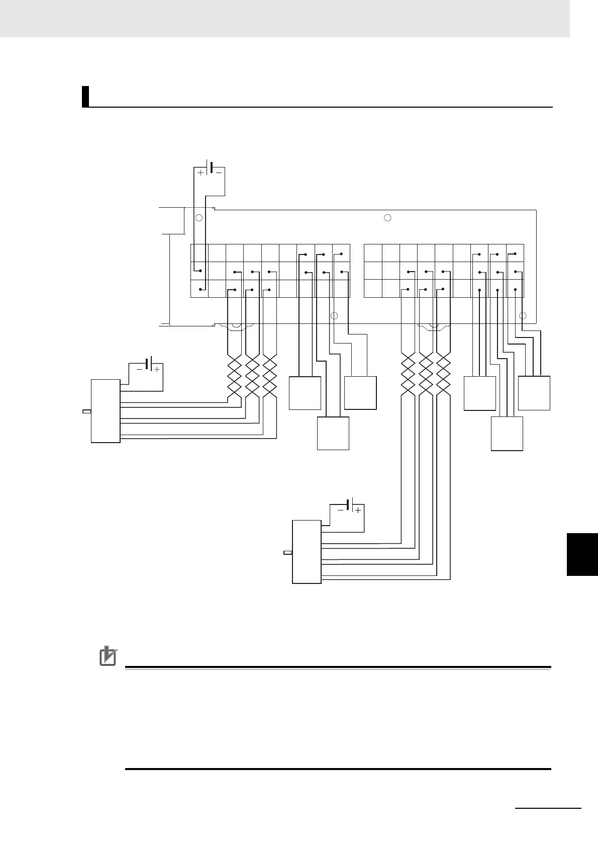
9-4-2 Line Driver Input Type GX-EC0241
Precautions for Correct Use
• Use shielded cable and ground the shield to 100 Ω or less when wiring pulse input A/B/Z with
external control inputs.
• Wiring of pulse input A/B/Z shall be as short as possible and separated from wiring with many
noises such as power lines.
• Use stabilizing power supply separate from other inputs/outputs for Encoder Input Slave Units
as much as possible.
• Do not wire anything to RSV terminals.
Wiring diagram
RSV
RSV RSV RSV RSV
RSV LA1 LB1
RST1
V1 V1
A
+
B
+
Z
+
V1 V1 V1
G1 G1
A
−
B
−
Z
−
G1 G1 G1
V1
G1
RSV
RSV RSV RSV RSV
RSV LA2 LB2
RST2
V1 V1
A
+
B
+
Z
+
V1 V1 V1
G1 G1
A
−
B
−
Z
−
G1 G1 G1
V1
G1
Encoder
(Line driver
output type)
Encoder power supply
(5 VDC)
Blue
:
0V
Brown
:
Vcc
Black
:
Phase A+ Black/Red
:
Phase A−
Internal circuit /
sensor power supply
(24 VDC)
Encoder
(Line driver
output type)
White
:
Phase B+ White/Red
:
Phase B−
Orange
:
Phase Z+ Orange/Red
:
Phase Z−
Encoder power supply
(5 VDC)
Phase
A
Phase
B
Phase
Z
Black
Blue
Latch
Black
Blue
Reset
Black
Blue
Latch
Output
2-wire sensor
NPN output
3-wire sensor
Black
Brown
Blue
Latch
Black
Brown
Blue
Latch
Black
Brown
Blue
Reset

 Loading...