3 Functions of NB-Designer
3-254
NB-series Programmable Terminals NB-Designer Operation Manual(V106)
Function Mode
1
Switch Screens
This operation needs 2 consecutive word addresses. When the [Read Address] is switched to
a valid screen No., the current screen will be closed and the specified screen will appear.
Specify the number in the destination screen in the [Read Address]. The number after
switching will be written in [Read Address + 1]
For example, set the address to “LW0”, Data Format to “BCD” and the current screen to Frame
0. If LW0 is changed to 10, the current screen will be switched to Frame 10, and 10 will be
returned to LW1.
Note Each time the [Change Screen] Function Key is pressed, the current screens is closed and the destination
screen is displayed. The function of [Switch Screens] of the PLC control is similar to the [Change Screen]
function of the Function Key. Their difference is the respect whether function is operated by touching the
screen or it is performed by the PLC memory control. When the value of Read Address is modified to an
available screen No., the current screen will be closed and the screen specified with the Read Address
will be displayed. Then the content of the Read Address in written in the Read Address + 1. This
operations can be executed only when the Read Address is modified.
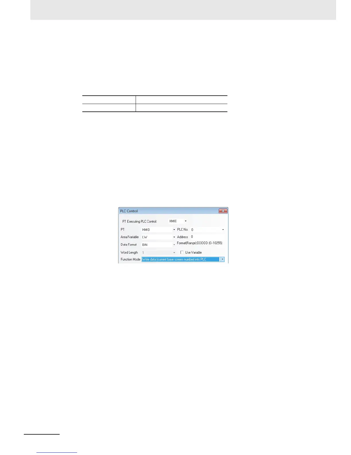
2
Write Data (Current Base Screen No.) into PLC
The number of the base screen currently displayed will be notified to the PLC.
When there is a PLC Control with the settings shown as above, word address LW0 will store
the No. of the current base screen.
3
General PLC Control
The data transmission between the PLC and the PT can be controlled.
It can be divided into 4 types according to the direction of data transmission:
(a) PLCRW (Recipe Data Memory), type code 1.
(b) PLCLW (Local Data memory of PT), type code 2.
(c) RW (Recipe Data memory)PLC, type code 3.
(d) LW (Local Data memory of PT)PLC, type code 4.
The specific instructions are as follows:
Select “General PLC Control” as “Control Type” in PLC Control setting dialog box, and select
the data area and the address of the data transmitted by the [Read Address]. Please note that
the unit must be “word”, and the system automatically allocate 4 continuous addresses, which
are used as the controlling addresses of the data transmission. And the specific meanings and
usage methods are as follows:
(1) Read Address: Select the 4 types of execution type codes. When new value is written to the
memory, the system execute the corresponding transmission function. After the
transmission is completed, the memory will be reset to 0.
(2) Read Address + 1: Specify the size of the data transmitted. The number of the word
specified at this moment will be transmitted.
Read Address For screen switching control
Read Address + 1 No. of the destination screen

 Loading...


