2-2 Part Names and Functions
2-19
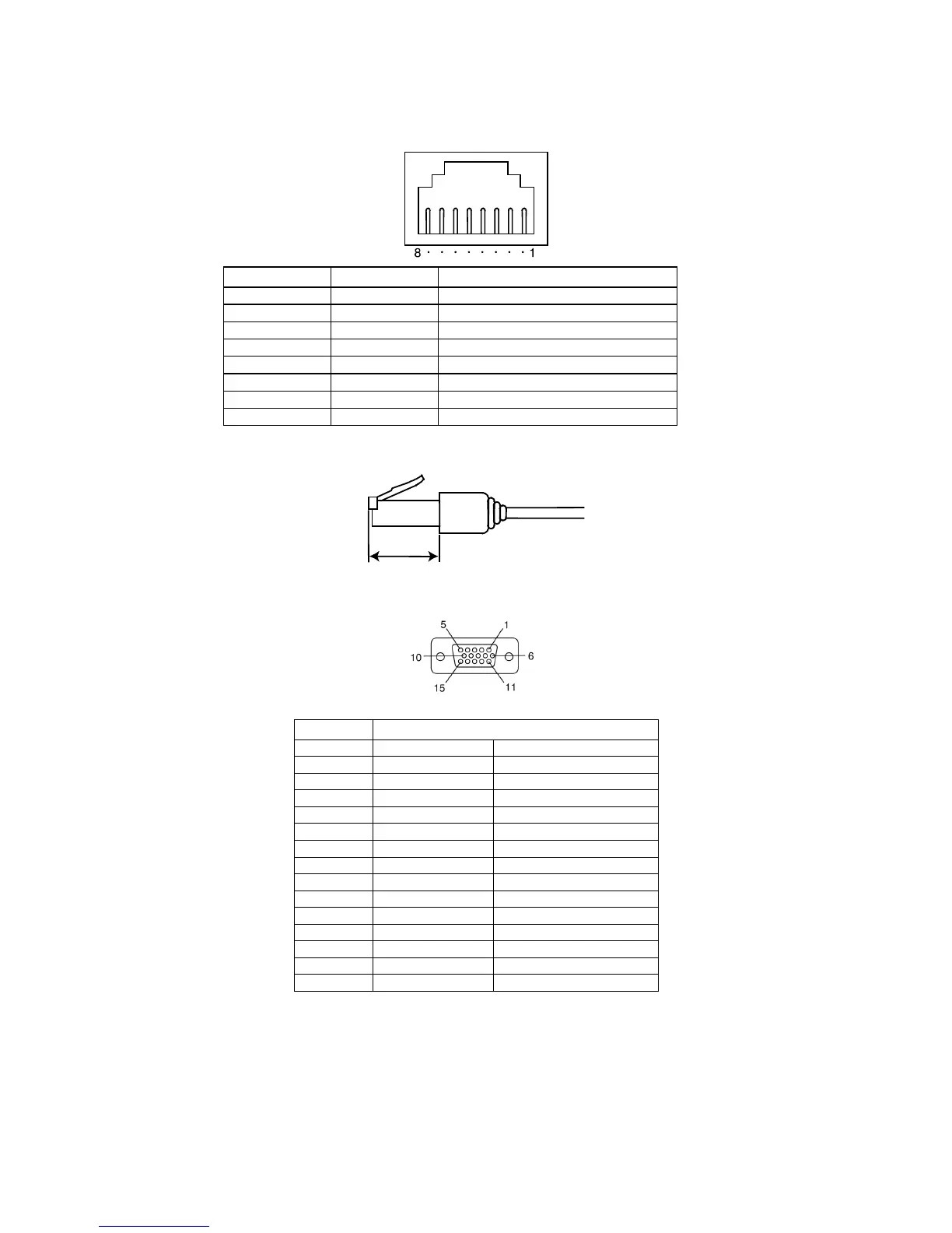
Ethernet Connector Pin Arrangement
Pin number Signal name Name
1 TD+ Twisted-pair output (differential output)
2
TD
−
Twisted-pair output (differential output)
3 RD+ Twisted-pair input (differential input)
4 BI_D+ Protection circuit
5
BI_D
−
Protection circuit
6
RD
−
Twisted-pair input (differential input)
7 BI_D+ Protection circuit
8
BI_D
−
Protection circuit
When using a cable with a hood (or boot), make sure that the length for connection is at
least 15 mm, as shown in the following diagram.
15 mm min.
Analog GRGB output connector (NS15 Only)
Pin No. Signal name
1 GND GND
2 NC Not used
3 BLUE Blue video signal
4 GREEN Green video signal
5 RED Red video signal
6 GND GND
7 NC Not used
8 B_GND Blue video signal GND
9 G_GND Green video signal GND
10 R_GND Red video signal GND
11 NC Not used
12 VSYNC Vertical sync signal
13 HSYNC Horizontal sync signal
14 NC Not used
15 NC Not used
External Brightness Adjustment Connector (NS15 Only)
You can connect this connector to an external variable resistor to adjust the brightness of the
backlight of the PT.