Battery-related Error Detection and Clock Data Settings
Because the CPU Unit is shipped with the battery not mounted, the Battery-related error detection is
set to Do not use by default.
The behavior of the CPU Unit when a battery-related error is detected depends on whether battery er-
ror detection is used or not used as shown in the table below.
When the battery is not mounted, you can set the
Battery-related error detection to Do not use to
suppress battery errors.
When the battery is mounted, however, you can set the Battery-related error detection to Use to de-
tect battery errors.
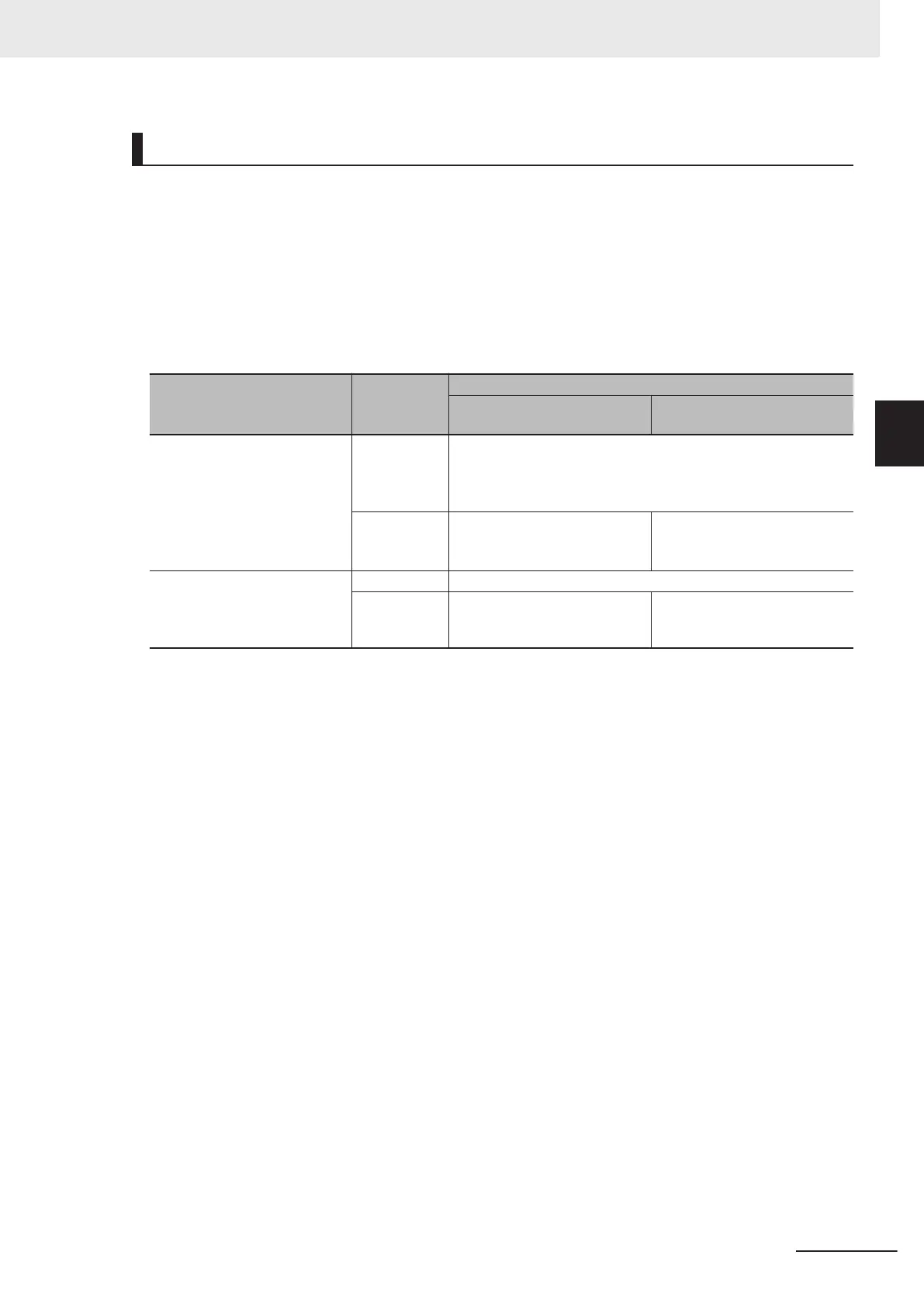
Cause of error
What is af-
fected
Behavior
When the Battery-related error
detection is set to Do not use
When the Battery-related error
detection is set to
Use
One of the following was detected
at power ON.
• Built-in capacitor discharged
• Battery not mounted
• Mounted battery discharged
Clock data
• In case of clock oscillator stopping
T
ime measurement starts from January 1st, 1970.
• In case of low battery voltage
T
ime measurement continues.
Error detection No error is detected. The following error is detected.
• Low Battery Voltage
• Real-Time Clock Stopped
One of the following was detected
after power ON.
• Battery was removed
• Mounted battery discharged
Clock data Time measurement continues.
Error detection No error is detected. The following error is detected.
• Low Battery Voltage
When you mount the battery, set the Battery-related error detection to Use.
The measurement of clock data starts from January 1st, 1970 if the clock oscillator stops. If this oc-
curs, readjust the CPU Unit’s clock data to the current time.
In order to use the clock data for programming, you need to use system-defined variables to read the
presence or absence of the Low Battery V
oltage and Real-Time Clock Stopped errors and confirm that
the clock data is normal.
Refer to the Sysmac Studio Version 1 Operation Manual (Cat. No. W504) for battery-related error de-
tection and clock data settings.
3 Configuration Units
3-19
NX-series NX1P2 CPU Unit Hardware User’s Manual (W578)
3-1 CPU Units
3
3-1-5 Battery
 Loading...


