4-2
Designing the NX Unit Power Supply
System
This section describes how to design the NX Unit power supply to the CPU Rack of the NX-series
NX1P2 CPU Unit.
4-2-1
Procedure for Designing the NX Unit Power Supply System
The total power consumption from the NX Unit power supply must not exceed the NX Unit power sup-
ply capacity of the Unit that supplies the NX Unit power.
Use the following procedure to design the NX Unit power supply.
1 Calculate the total power consumption from the NX Unit power supply that is required by the
NX Units that are connected to the CPU Unit.
2 If the total power consumption from the NX Unit power supply exceeds the NX Unit power sup-
ply capacity of the CPU Unit, add an Additional NX Unit Power Supply Unit to the right of an
NX Unit before the capacity is exceeded.
3 Calculate the total power consumption from the NX Unit power supply that is required by the
NX Units that are connected after the Additional NX Unit Power Supply Unit. If the total power
consumption of those NX Units exceeds the NX Unit power supply capacity of the Additional
NX Unit Power Supply Unit, add another Additional NX Unit Power Supply Unit to the right of
an NX Unit before the capacity is exceeded.
4 Repeat step 3 until the design conditions for the NX Unit power supply are met.
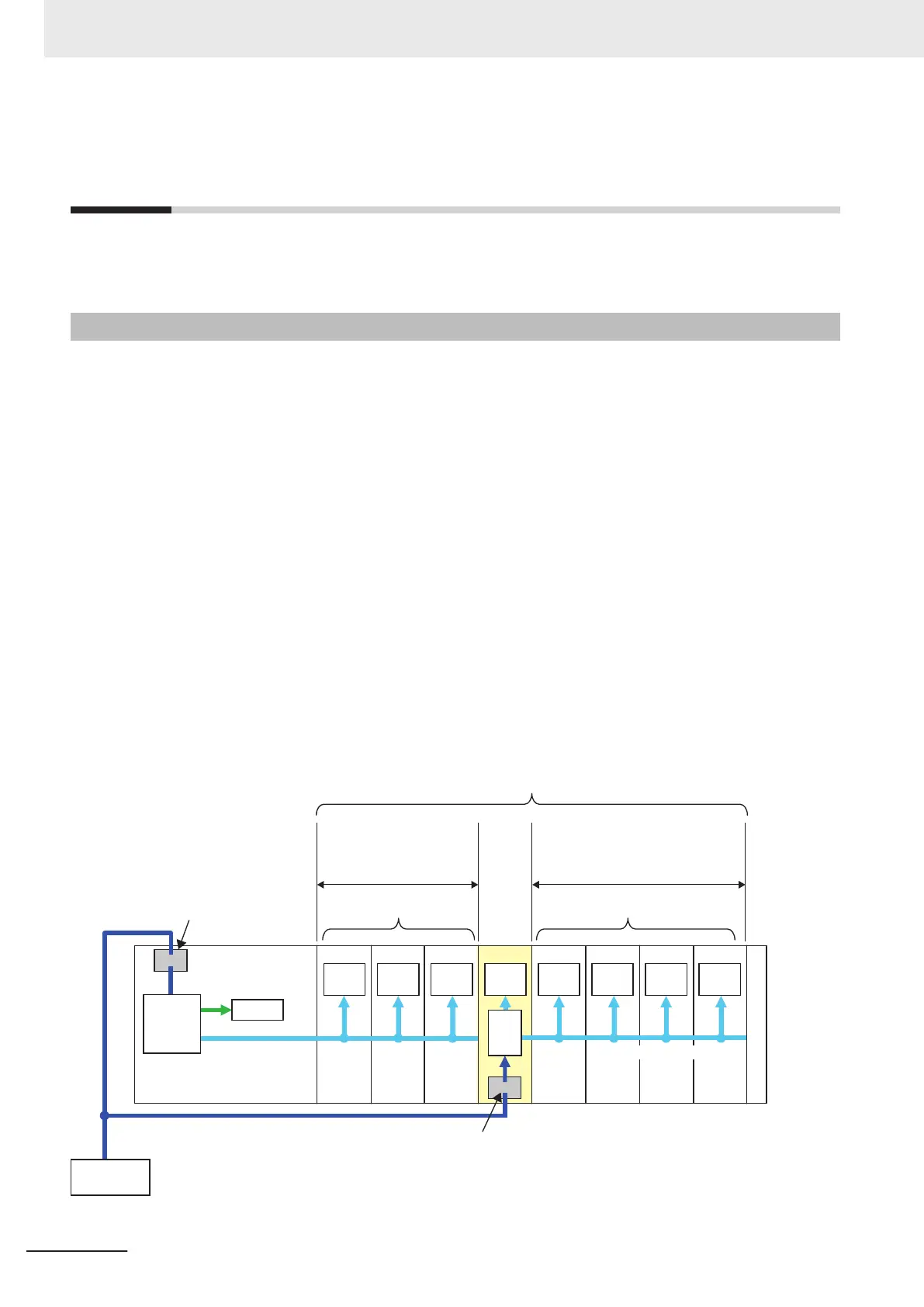
NX-series NX1P2
CPU Unit
Unit power supply terminals
NX Unit connected to
the CPU Unit
NX Unit connected to the Additional
NX Unit Power Supply Unit
Unit power supply terminals
The total power consumption
from the NX Unit power supply
must not exceed the NX Unit
power supply capacity.
The total power consumption from
the NX Unit power supply must not
exceed the NX Unit power supply
capacity.
Internal
power
supply
circuit
Internal
circuits
NX Unit power supply
Unit power
supply
(24 VDC)
Internal
circuits
Internal
circuits
Internal
circuits
Internal
circuits
Internal
circuits
Internal
circuits
Internal
circuits
Internal
circuits
NX Unit power supply
Internal
power
supply
circuit
8 max.
Addi-
tional
NX Unit
Power
Supply
Unit
End
Cover
○
○
4 Designing the Power Supply System
4-10
NX-series NX1P2 CPU Unit Hardware User’s Manual (W578)

 Loading...


