3-4-2
Purpose
The Analog I/O Option Board allows inputs from devices such variable resistors and process-control
sensors. It also enables you to control inverters.
Analog inputs that can be processed are 0 to 10 V inputs from devices including variable resistors,
and 4 to 20 mA inputs from process-control sensors.
Analog output range from 0 to 10 V
, which allow the CPU Unit to control inverters directly
.
Refer to the NX-series NX1P2 CPU Unit Built-in I/O and Option Board User’s Manual (Cat. No. W579)
for details on how to use the Option Boards.
3-4-3
Part Names and Functions
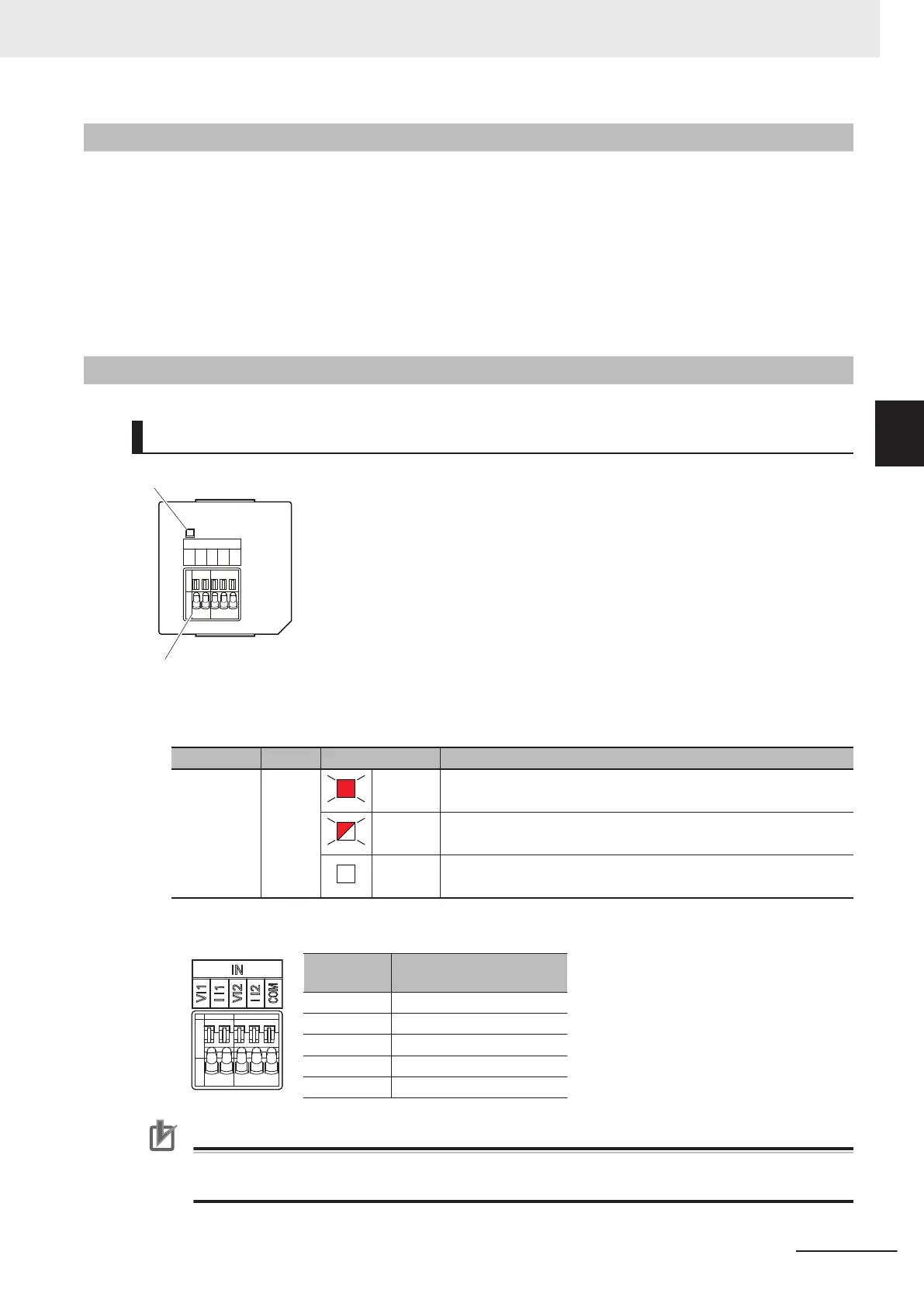
Analog Input Option Board (NX1W-ADB21)
ERR
IN
VI1
I I1
VI2
I I2
COM
Analog input terminal block
Status indicator
l
Status Indicator
Indicator Color Status Description
ERR Red
Lit. An Option Board error (WDT) was detected by the self-diagnostic func-
tion.
Flashing. A communications error occurred between the Option Board and the
CPU Unit.
Not lit. Normal operation
l
Analog Input Terminal Array
Abbrevia-
tion
Signal name
V I1 Voltage input 1
I I1 Current input 1
V I2 Voltage input 2
I I2 Current input 2
COM Input common
Precautions for Correct Use
When you use the current input, be sure to short-circuit V I1 with I I1, and short-circuit V I2 with
I I2.
3 Configuration Units
3-27
NX-series NX1P2 CPU Unit Hardware User’s Manual (W578)
3-4 Analog I/O Option Board
3
3-4-2 Purpose

 Loading...


