5-4-10
Wiring the NX1W-CIF01 Serial Communications Option Board
This section explains the wiring of an NX1W-CIF01 Serial Communications Option Board.
Caution
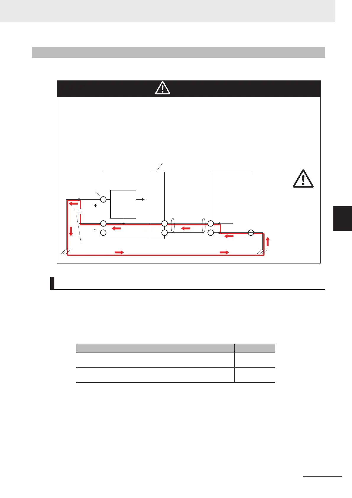
When you connect a computer or other peripheral device to a Controller that has a
non-isolated DC power supply
, either ground the 0-V side of the external power supply
or do not ground it at all.
If the peripheral devices are grounded incorrectly
, the external power supply may be
short-circuited. Never ground the 24-V side of the power supply, as shown in the fol-
lowing figure.
Internal
power supply
circuit
(Non-isolated)
CPU Unit
Cable
External device
(e.g. computer)
External power supply (Unit power supply)
Non-isolated Option Board,
Communications Interface Unit, etc.
Unit power
supply terminals
Non-isolated DC
power supply
Recommended RS-232C Wiring
We recommend the following wiring method for the RS-232C, especially in environments prone to
noise.
1 Use shielded twisted-pair cables for the communications cables.
•
Recommended RS-232C Cables
Model numbers Manufacturer
UL2464 AWG28x5P IFS-RVV-SB (UL product)
AWG28x5P IFVV
-SB (non-UL product)
Fujikura Ltd.
UL2464-SB (MA) 5Px28AWG (7/0.127) (UL product)
CO-MA-VV-SB 5Px28A
WG (7/0.127) (non-UL product)
Hitachi Cable,
Ltd.
2 Combine a signal wire and SG (signal ground) wire in a twisted-pair cable. At the same time,
bundle the SG wires at the connectors on Option Board and the remote device.
3 Connect the SHLD of the communications cable to the SHLD on the Option Board.
5 Installation and Wiring
5-69
NX-series NX1P2 CPU Unit Hardware User’s Manual (W578)
5-4 Wiring
5
5-4-10 Wiring the NX1W-CIF01 Serial Communications Option Board

 Loading...


