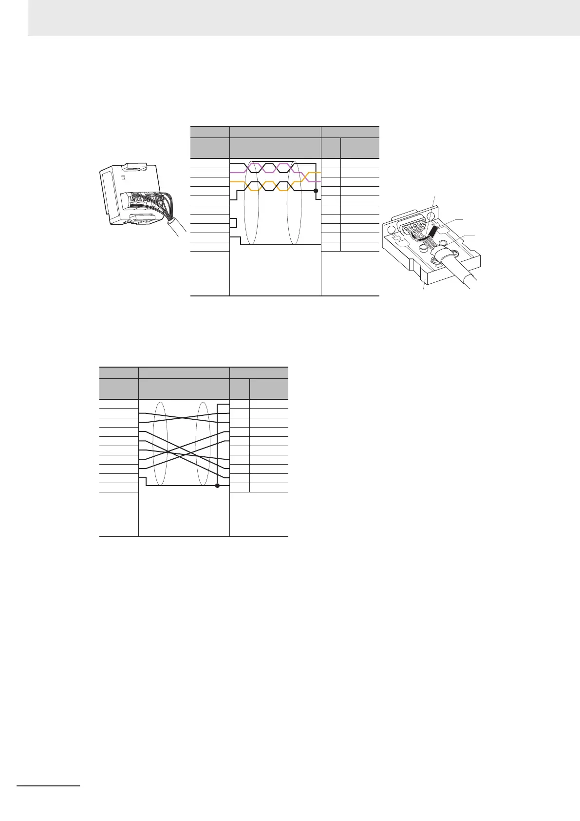
EasyManuals Logo

Omron NX1P2 series Hardware User Manual

Omron NX1P2 series
264 pages
To Next Page IconTo Next Page
To Previous Page IconTo Previous Page
Page #214 background imageLoading...
Page #214 background image
l
Connection Example
Example: Twisted-pair cable connecting SD-SG, and RD-SG terminals when serial communica-
tions mode is the host link.
CIF01 side
Signal
Cable
Wiring example
Computer side
Signal
Pin
No.
Shell
Screwless
clamping
terminal
block (9 pin)
D-sub
9 pin (female)
SG0
RD
SD
ER
SG1
DR
RS
CS
SHLD
CD
RD
SD
ER
SG1
DR
RS
CS
CI
1
2
3
4
5
6
7
8
9
-
SG signal wires
Bundle the
SG wires
Aluminum
foil
XM2S-0911-E
Example: When using cables and devices that you used with CS/CJ/CP Series.
Prepare a cable to convert the terminal block on the Serial Communications Option Board into the
D-sub9 for CS/CJ/CP Series.
CIF01 side
Signal
Cable
Wiring Example
Computer side
Signal
Pin
No.
Shell
Screwless
clamping
terminal
block (9 pin)
D-sub
9 pin (female)
SG0
RD
SD
ER
SG1
DR
RS
CS
SHLD
FG
SD
RD
ER
CS
5V
DR
ER
SG
1
2
3
4
5
6
7
8
9
-
5 Installation and Wiring
5-70
NX-series NX1P2 CPU Unit Hardware Users Manual (W578)

Table of Contents

Other manuals for Omron NX1P2 series

Questions and Answers:

Question and Answer IconNeed help?

Do you have a question about the Omron NX1P2 series and is the answer not in the manual?

Omron NX1P2 series Specifications

General IconGeneral
ModelNX1P2 Series
ManufacturerOmron
TypeController
CPU Units1
Program Capacity5 MB
Data Memory Capacity128 KB
Ethernet Ports1
Serial Ports1
Built-in EtherNet/IP PortYes
Built-in EtherCAT PortYes
Built-in USB PortYes
SD Memory Card SlotYes
USB Port1
Power Supply Voltage24 VDC
Programming LanguageLadder, Structured Text, Function Block Diagram
Communication ProtocolsEtherNet/IP, EtherCAT, Serial (RS-232C)

Related product manuals