Wiring to Terminal Block of the NX1W-CIF01
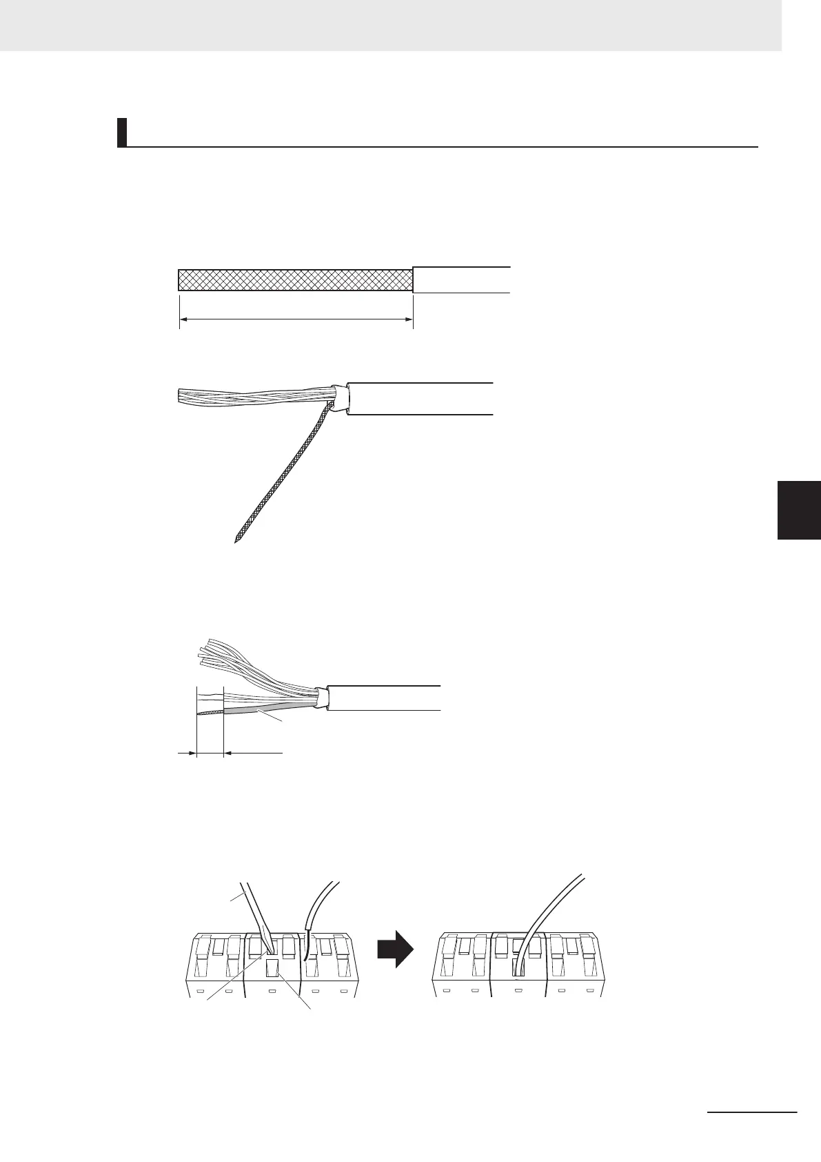
1 Cut the cable to the required length.
2 Remove the specified length of the sheath.
Be careful not to scratch the braided shield.
3 Unbraid and put up the braided shield.
4 Remove the insulation from each core wire using a stripper.
Cover the braided shield with a heat-shrinking tube (3.0 dia.), and heat the tube to shrink it in
place.
Heat-shrinking tube
8 to 9 mm
5 Using a thin flat-blade screwdriver, press in the release button of the terminal block. Insert the
cable core wire into the terminal hole.
Confirm that the core wire exposed part is fully inserted into the terminal hole, and then release
the release button.
Release button Terminal hole
Flat-blade
screwdriver
To remove the wire, press in the release button with a thin flat-blade screwdriver, and pull out
the wire while it is unlocked.
5 Installation and Wiring
5-71
NX-series NX1P2 CPU Unit Hardware User’s Manual (W578)
5-4 Wiring
5
5-4-10 Wiring the NX1W-CIF01 Serial Communications Option Board
 Loading...


