5-4-12
Wiring the Analog I/O Option Board
This section explains the wiring of an NX1W-ADB21/-DAB21V/-MAB221 Analog I/O Option Board.
An Analog I/O Option Board provides analog input and analog output. For all models, the same meth-
od is used to connect analog input and analog output.
Refer to 3-4 Analog I/O Option Board on page
3-26 for the terminal arrangement for each model of the
Analog I/O Option Board.
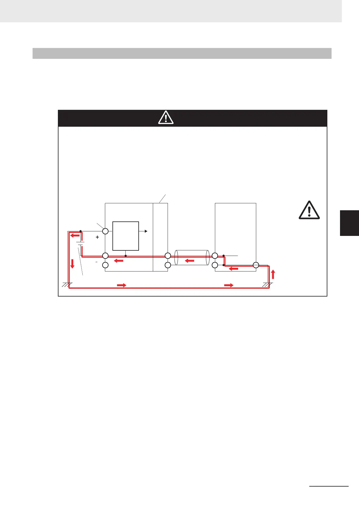
Caution
When you connect a computer or other peripheral device to a Controller that has a
non-isolated DC power supply
, either ground the 0-V side of the external power supply
or do not ground it at all.
If the peripheral devices are grounded incorrectly
, the external power supply may be
short-circuited. Never ground the 24-V side of the power supply, as shown in the fol-
lowing figure.
Internal
power supply
circuit
(Non-isolated)
CPU Unit
Cable
External device
(e.g. computer)
External power supply (Unit power supply)
Non-isolated Option Board,
Communications Interface Unit, etc.
Unit power
supply terminals
Non-isolated DC
power supply
5 Installation and Wiring
5-77
NX-series NX1P2 CPU Unit Hardware User’s Manual (W578)
5-4 Wiring
5
5-4-12 Wiring the Analog I/O Option Board
 Loading...


