l
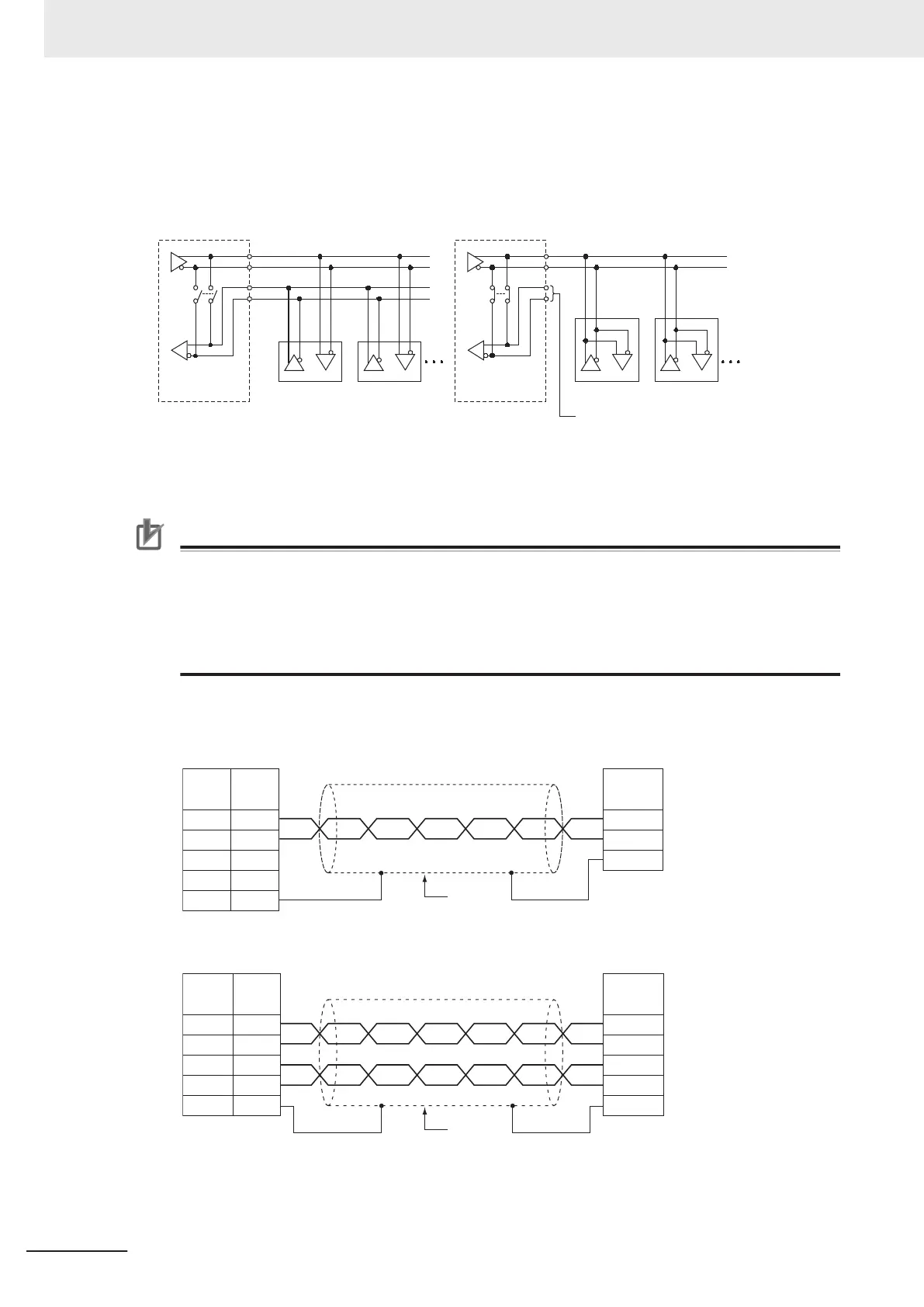
Connection Examples: Two-wire and Four-wire Transmission Circuits
The transmission circuits for two-wire and four-wire connections are different, as shown in the fol-
lowing diagram.
Example of Four-wire Connections
Example of Two-wire Connections
Two/four-wire
switch
Option Board
Two/four-wire
switch
Option Board
Other Unit
Other UnitOther Unit
Other Unit
Connect to one of a pair
SD
A+/- or RDA+/-.
Set a terminating resistance if it is the end of transmission circuit.
Precautions for Correct Use
• Use the same type of transmission circuit (two-wire or four-wire) for all nodes.
•
Do not use four-wire connections when the two/four-wire switch on the Board is set to two-
wire.
•
Always install a terminating resistance on the last RS-422A/485 node. Refer to the NX-series
NX1P2 CPU Unit Built-in I/O and Option Board User’s Manual (Cat. No. W579) for details on
the wiring example of a terminating resistance.
l
Wiring Example: 1:1 Connections
a. Two-wire Connections
SDA -
SDB +
RDA -
RDB +
SHLD
3
4
1
2
5
FG
A(–)
B(+)
RS-422A/485 Option Board
Pin Signal
Signal
Shield
Remote device
Ground the shield at one end
when using NX1W
-CIF12.
b. Four-wire Connections
SDA-
SDB+
RDA-
RDB+
SHLD
3
4
1
2
5
RDA
RDB
SDA
SDB
FG
RS-422A/485 Option Board
Pin Signal Signal
Shield
Remote device
Ground the shield at one end
when using NX1W-CIF12.
5 Installation and Wiring
5-76
NX-series NX1P2 CPU Unit Hardware User’s Manual (W578)

 Loading...


