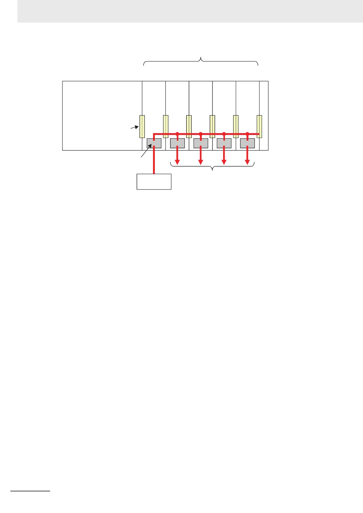
NX Units (8 max.)
To external devices
End Cover
I/O power supply
terminals
NX bus connector
NX-series
NX1P2 CPU
Unit
Additional I/O Power
Supply Unit
I/O power supply
(24 VDC, etc.)
○ ○ ○ ○ ○
I/O power
l
Additional Supply of I/O Power
In the following cases, you need another Additional I/O Power Supply Unit in addition to the one
inserted on the right side of the CPU Unit.
•
Over 4 A is consumed in total by the I/O circuits of the NX Units on the CPU Rack and external
devices connected to the NX Units.
• The I/O power voltage goes below the voltage levels specified for the I/O circuits of the NX Units
on the CPU Rack or those specified for the connected external devices.
Assume that three NX Units, No.1 to No.3, are connected to the CPU Rack, as shown below. Also
assume that only NX Unit No.1 is supplied with adequate current and voltage because one existing
Additional I/O Power Supply Unit and one external I/O power supply device cannot cover the total
current consumption of the I/O circuits of the three NX Units, the total current consumption of the
connected external devices, or I/O power voltage. In this case, insert another Additional I/O Power
Supply Unit between NX Units No.1 and No.2. Connect its I/O power supply terminals to an I/O
power supply device which is prepared separately from the one connected to the existing Addition-
al I/O Power Supply Unit. The I/O power is supplied to NX Units No.2 and No.3 via the inserted
Additional I/O Power Supply Unit.
More than one Additional I/O Power Supply Unit can be connected to the CPU Rack. If adequate
I/O power is not provided for all the NX Units on the right side of the Additional I/O Power Supply
Unit, add another Additional I/O Power Supply Unit to an appropriate place.
Basically, the I/O power supply line connects adjacent NX Units through the NX bus. However, the
I/O power supply line is separated by an inserted Additional I/O Power Supply Unit. In the figure
below, the I/O power supply line is separated between NX Unit No.1 and the Additional I/O Power
Supply Unit. However, the NX Unit power supply line is not separated by the Additional I/O Power
Supply Unit. Therefore, the NX unit power supply line is connected through all the NX Units, No.1
to No.3, as shown below.
4 Designing the Power Supply System
4-6
NX-series NX1P2 CPU Unit Hardware User’s Manual (W578)
 Loading...


